![]()
![]()
![]()
![]()
![]()
![]()
|
|
|
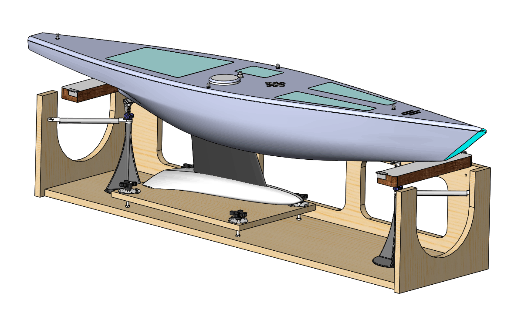
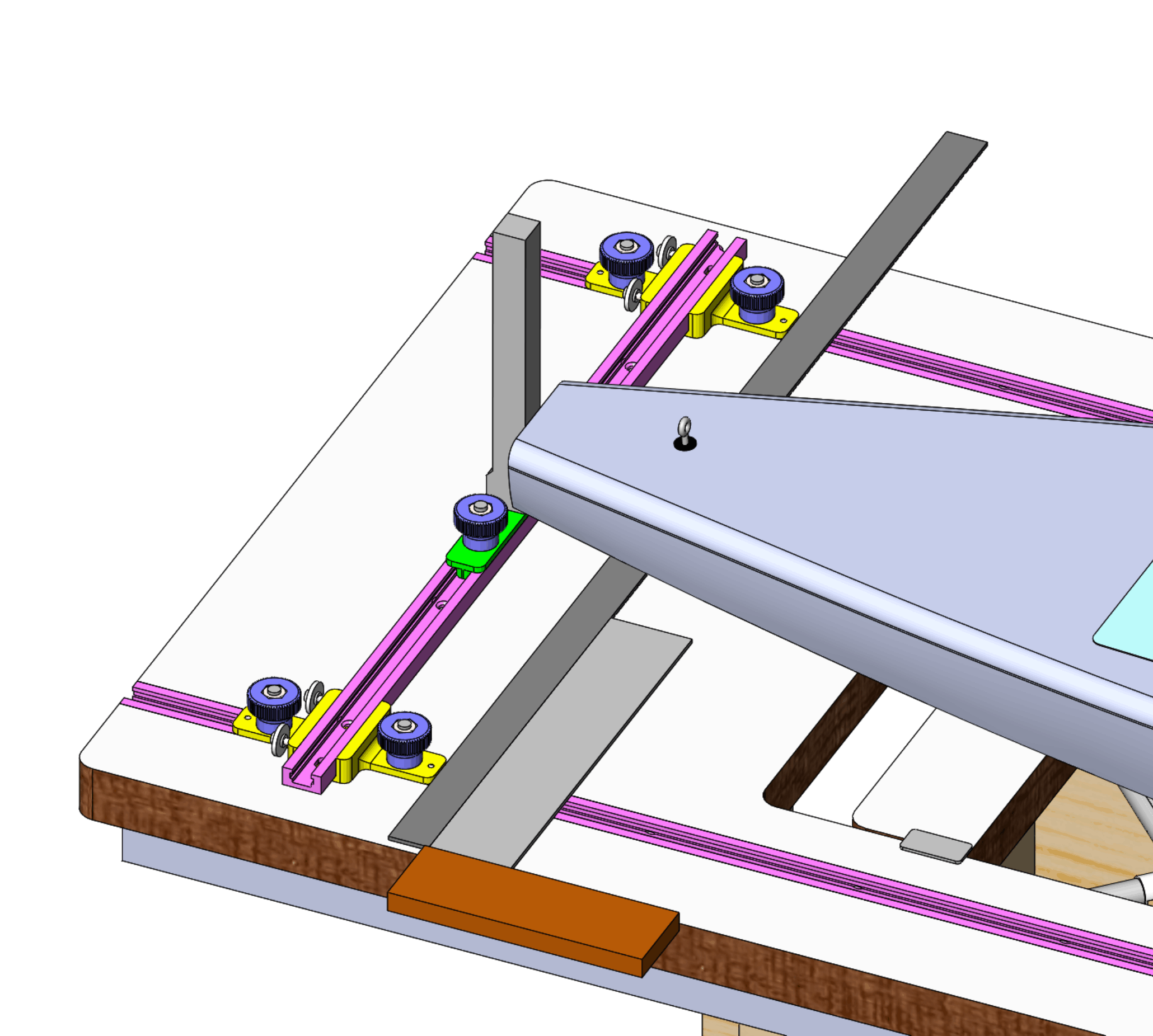
(The previous page dealt with establishing the 6M water line endings in the flotation tank.) Positioning the boat in the jigThe boat is placed in the dry measurement jig for the next measurement processes. The jig table top represents the water plane, so the boat must be positioned with its water line endings resting on fore and aft table top edges. This needs one or other jig top insert to be put in place and adjusted to suit, helped by resting the hull on fore and an aft stands with thumb wheels to adjust the stand height, as illustrated in Figure 1.
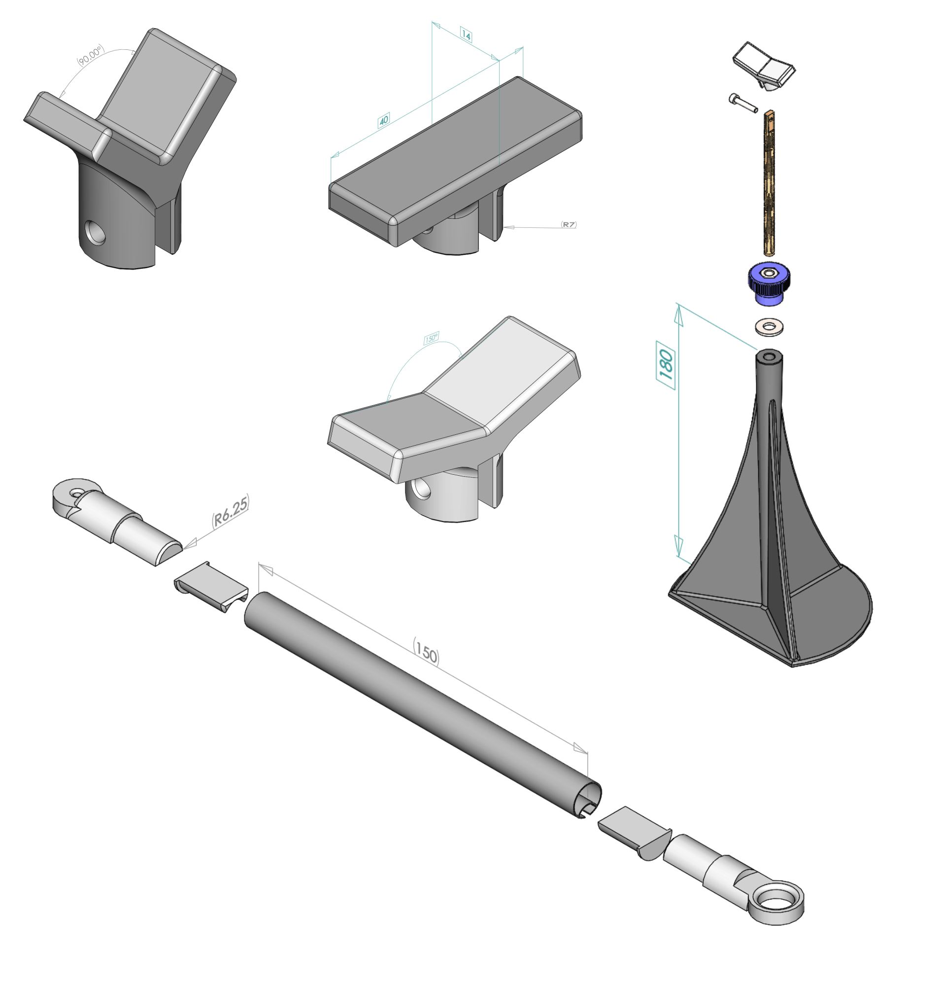
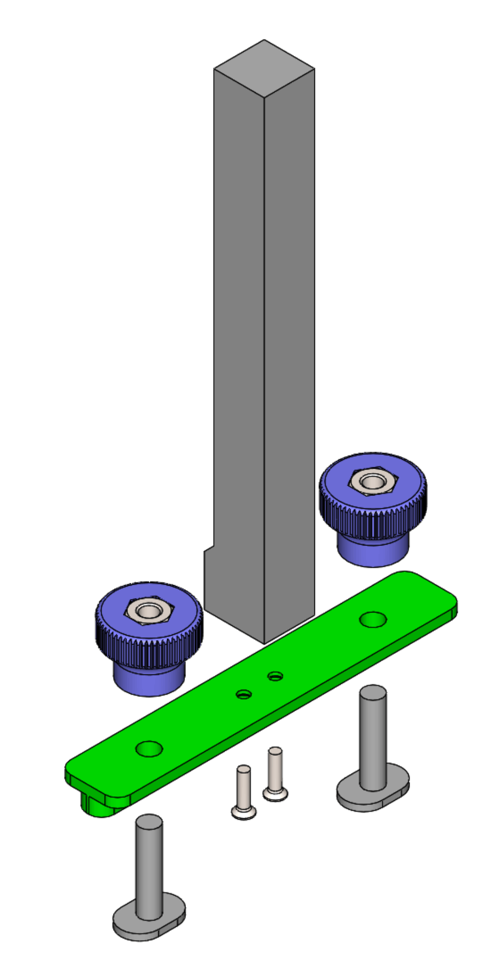
Figure 1. Boat positioned in dry measurement jig. Details of the stands are shown in Figure 2. The locating arms key to "L" hooks in the corners of the jig. The arm body is a scrap piece of mast tube. Download STLs for the 180° rest, 150° rest, 90° rest, stand base, arm end L, arm end knob collar, arm end packing piece, hand nut for stand. The hand nut features a lengthened collar that engages with the arm ends, where one arm is placed on top of the other arm rotated 180° to form the "V" at the hand nut.
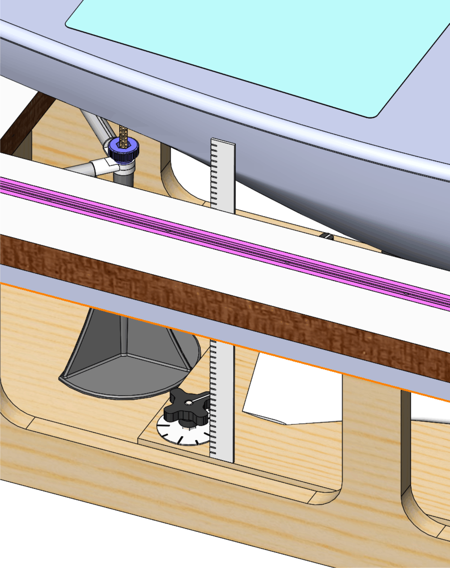
Figure 2. Stand and locating arm detail. Measuring draftThe draft is measured as illustrated in Figure 3. With the draft plate adjusters indexed to their dials as described in the previous page, the plate is moved up or down as needed with simultaneous turns of the adjusters until the keel is just touching the plate.
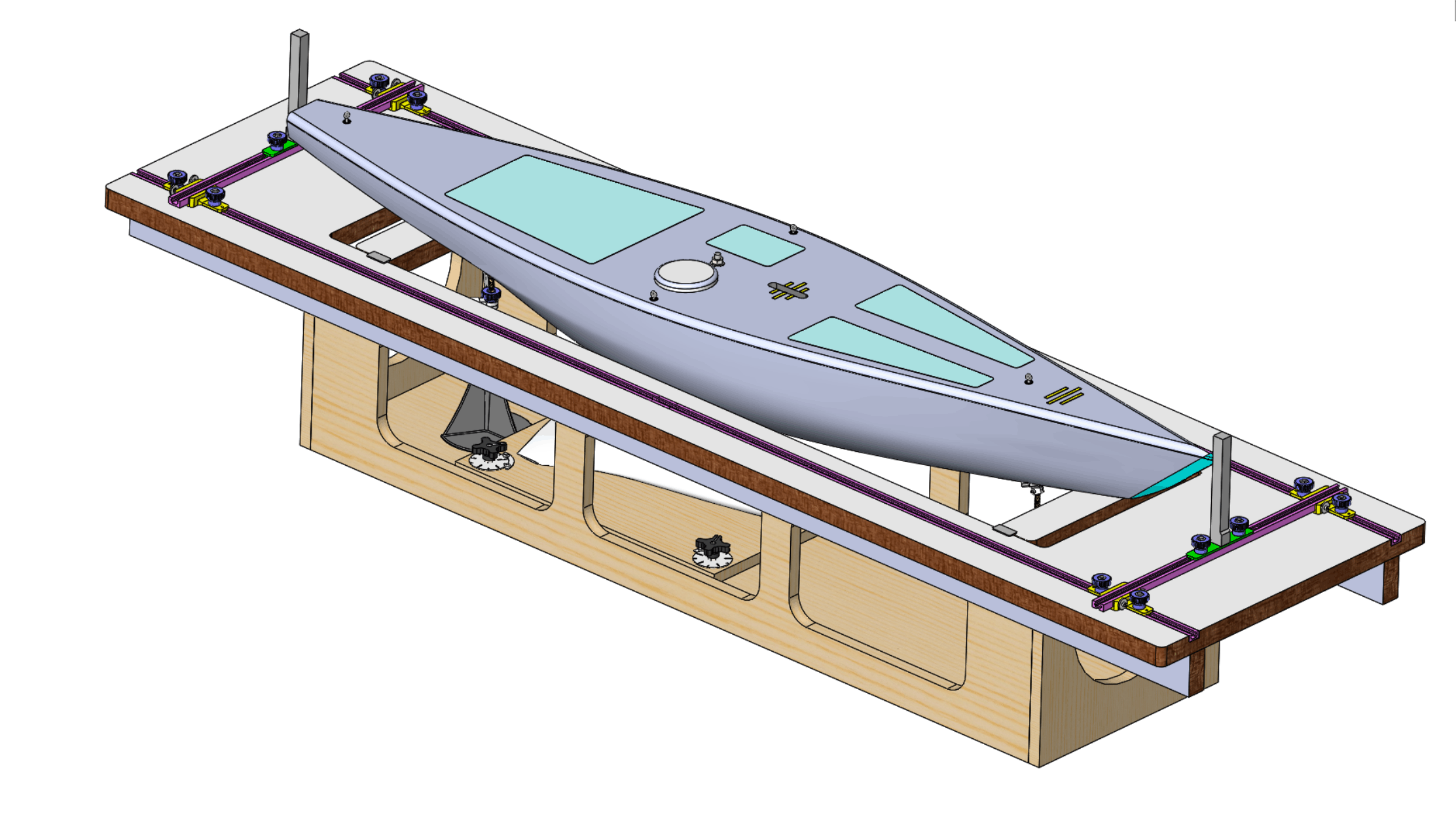
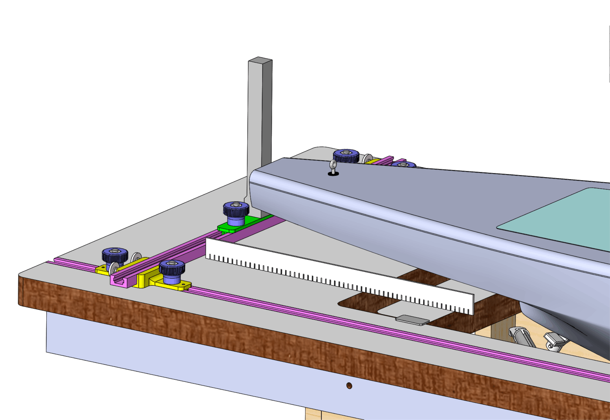
Figure 3. Measuring the draft. Measuring length overallTwo uprights are brought into contact with the extreme fore and aft ends of the hull, as illustrated in Figure 4. Length overall is then measured using a (Class I) tape measure.
Figure 4. Measuring length overall (LOA). As here and with subsequent measurement equipment, the indicators are positioned on a length of T-track bar which runs across the jig. An upright indicator has one face which is flush with the side of the T-track, allowing measurement to be taken along the length of the jig by reference to the T-track cross-bars. (LOA measurement can also be taken directly by reference to the uprights.) The upright indicator is illustrated in Figure 5. Downloadable STLs for upright indicator, plate. The plate is screwed to the upright indicator using M3 screws intended for plastic parts. These screws have a particularly wide helix with a particularly "fast" angle of thread. Accu calls them "Polyfix 30° Thread Profile Torx Countersunk". Similar screws from Westfield Fasteners who call them "Thread Forming Screws for Plastics". Conventional M6 x 12 T-bolts run in the cross-track bar, secured by the hand nuts shown earlier.
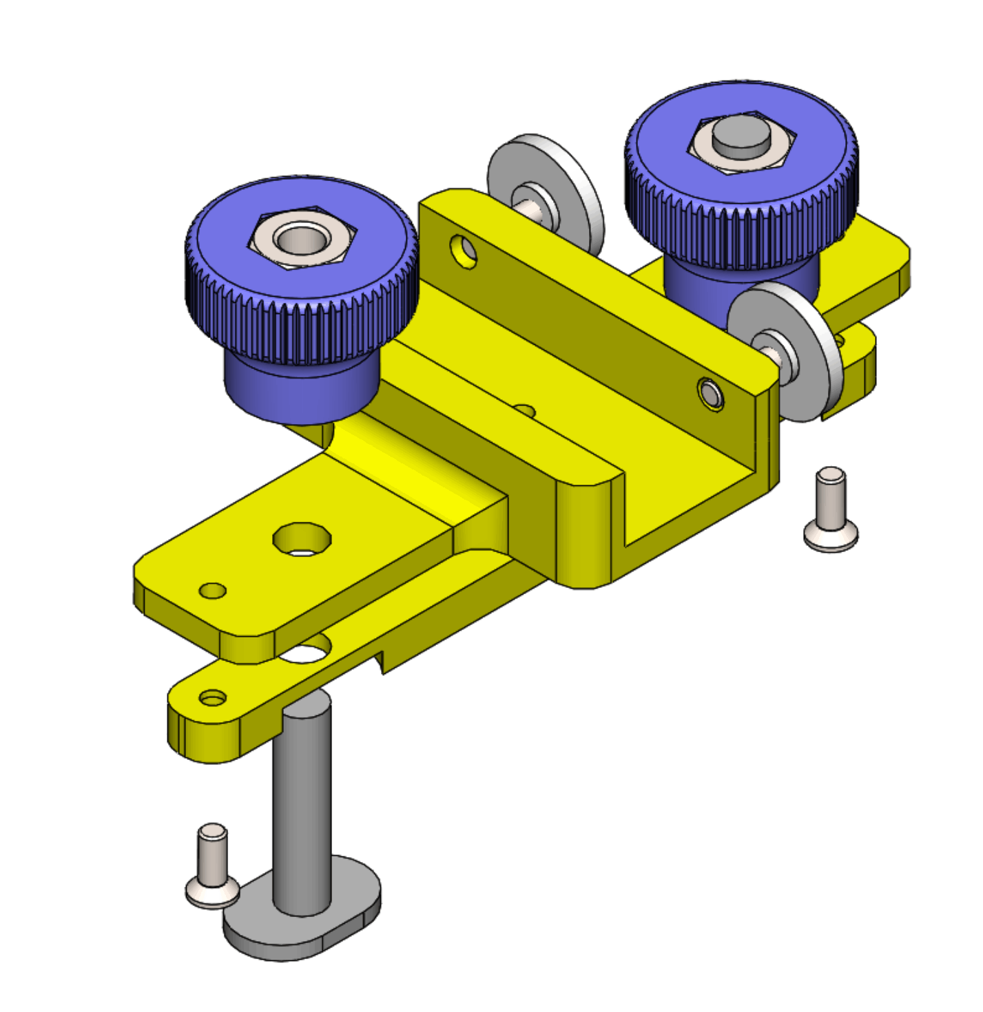
Figure 5. Upright indicator. As here and in subsequent measurement stages, the cross-bar is positioned and held in the jig side T-tracks by a pair of carriers, as illustrated in Figure 6. Downloadable STLs for the carrier body, carrier tongue. The carrier tongue is screwed to the carrier body using M3 "Polyfix" screws.
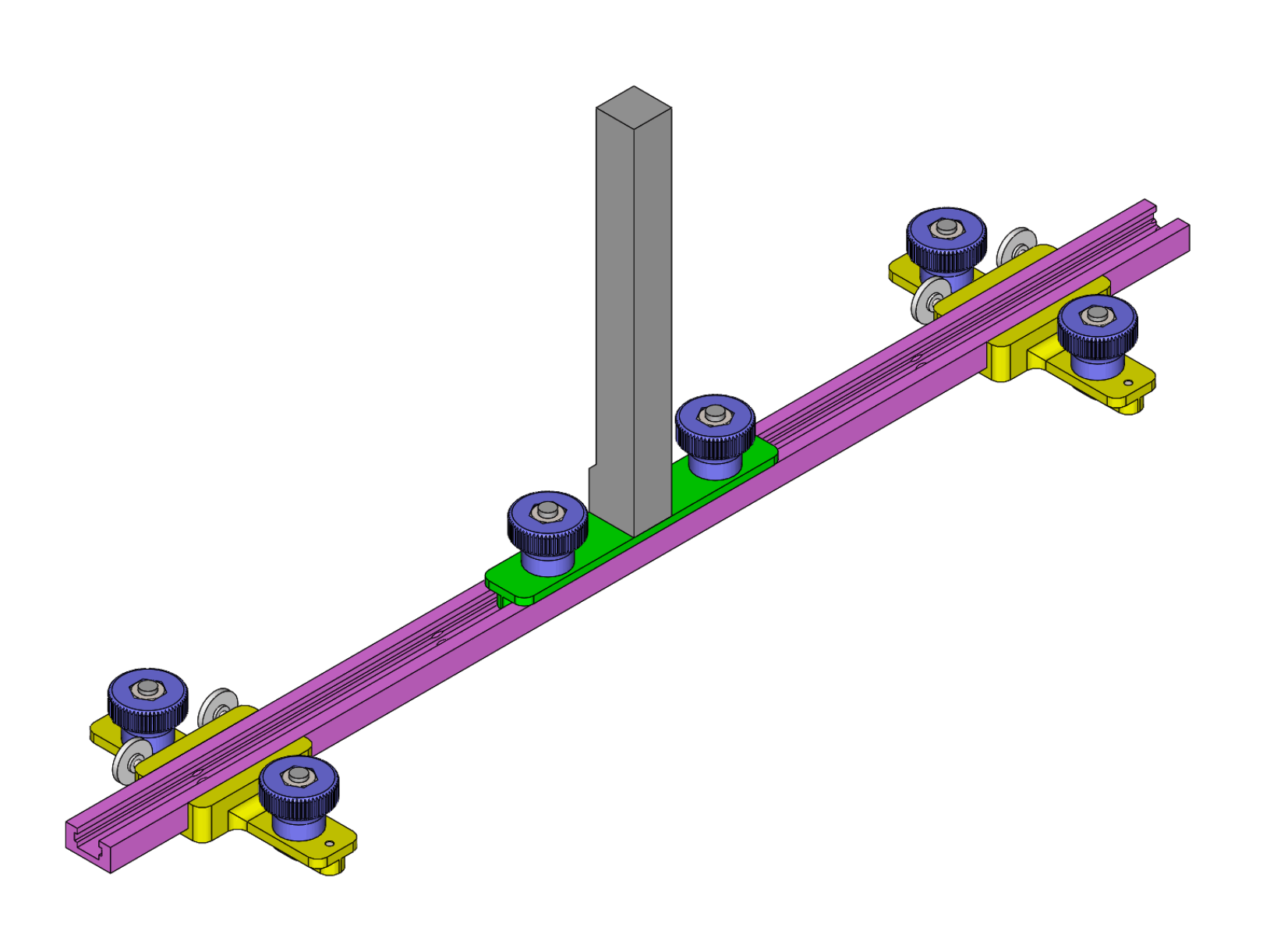
Figure 6. Cross-track carrier. The cross-track assembly at one or other end of the jig for measuring LOA is illustrated in Figure 7.
Figure 7. Cross-track assembly for LOA measurement. As here and in subsequent measurement stages, the cross-track assembly needs to be trued to the jig before being locked in place using a 600 mm ruler and a engineering square, as illustrated in Figure 8.
Figure 8. Cross-track assembly trued to jig side. And the uprights need to be checked that they are vertical, shown in Figure 9.
Figure 9. Checking vertical upright. OverhangsMeasurement of the fore and aft overhangs may be done with the LOA assemblies in place, as illustrated for the aft overhang in Figure 10.
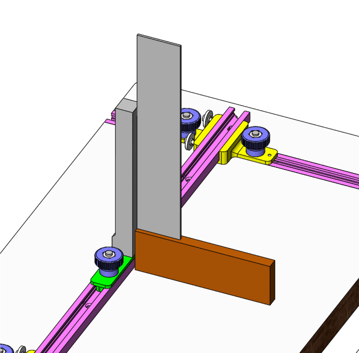
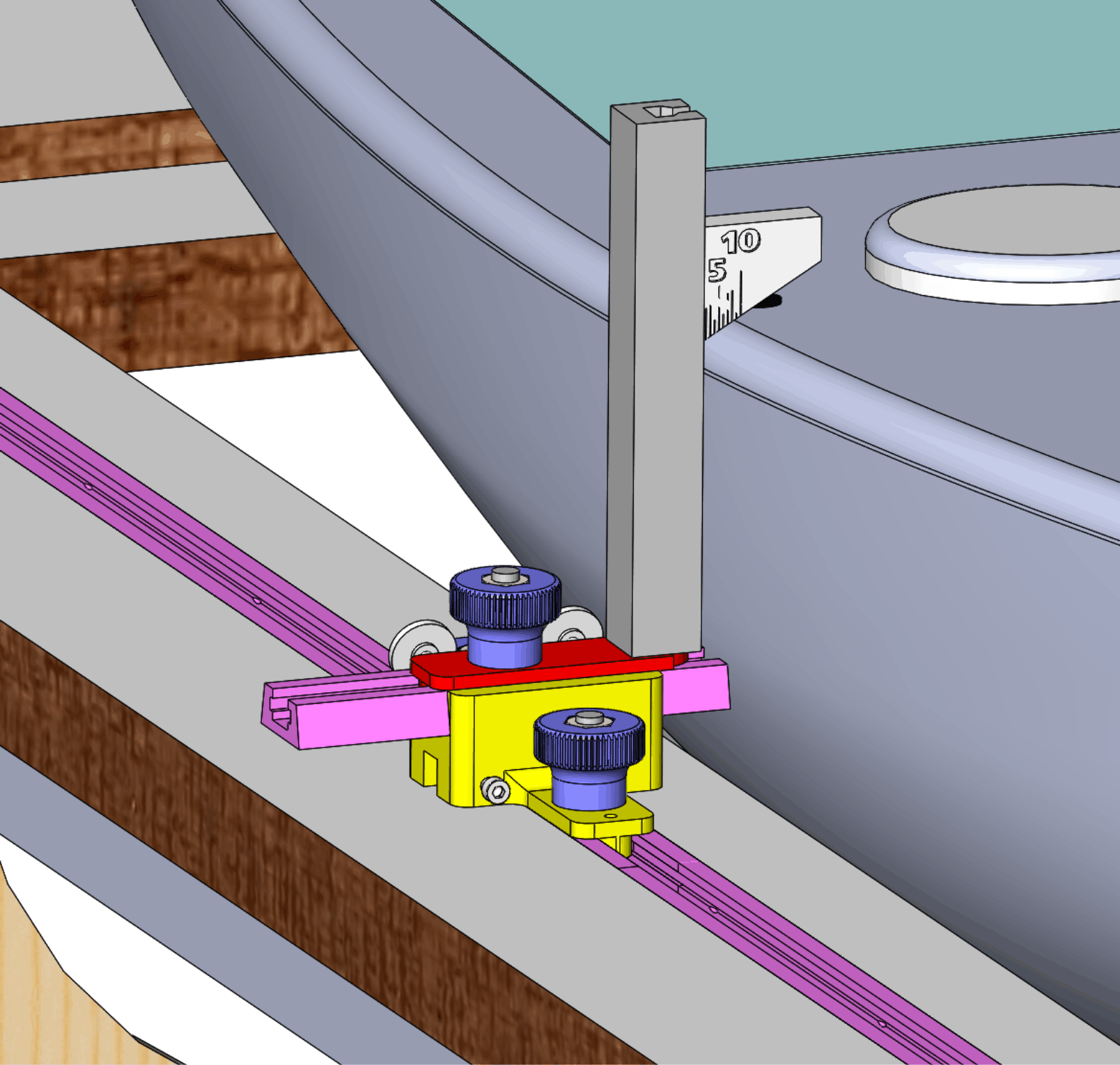
Figure 10. Measuring aft overhang. Maximum tumblehomeTumblehome is measured using an indicator with a surface angled at 30° and marks at 1 mm intervals, as illustrated in Figure 11. The tower is set against the side of the hull, possibly with a small pivot angle, and the indicator dropped down. Its point of contact with the hull identifies the deck edge. Note that the sheerline probably rises or falls in the vicinity of the indicator, hence the tumblehome reading must be taken at the side of the indicator which is in contact.
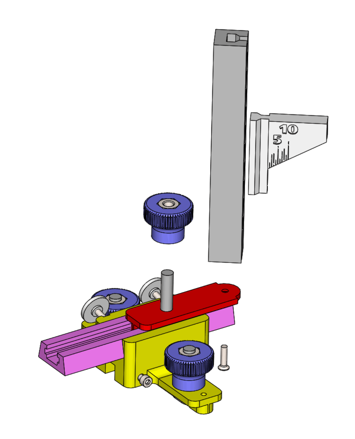
Figure 11. Measuring maximum tumblehome. The details of the tumblehome assembly are shown in Figure 12. The tower carrying the indicator can rotate on a single Polyfix screw to best present the indicating surface to the deck edge. Downloadable STLs for max TH indicator, pivotable tower, pivot plate. The carrier illustrated is for a short length of dovetail T-track, its details are given in the page dealing with Bow and girth station measurements.
Figure 12. Tumblehome assembly. Extreme beamExtreme beam can be measured in a variety of ways. If convenient, it may be done using the tumblehome assembly with the tower set against the side of the hull. Some designs have their extreme beam close to the water plane, however, lower than the bottom edge of the tumblehome assembly, in which case a longer offset tower may be set against the side of the hull. The required assembly is illustrated in Figure 13. Download STL offset pivot extended tower.
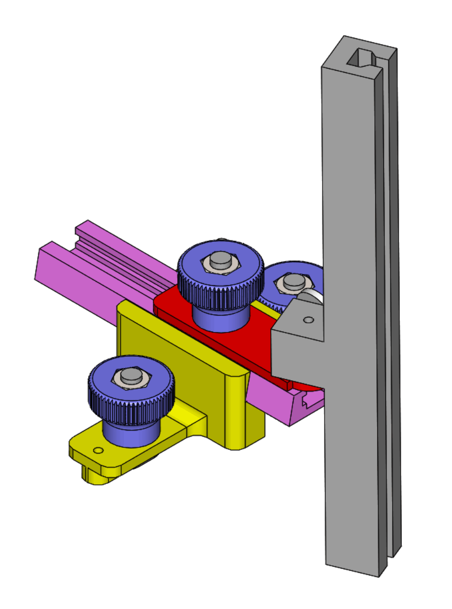
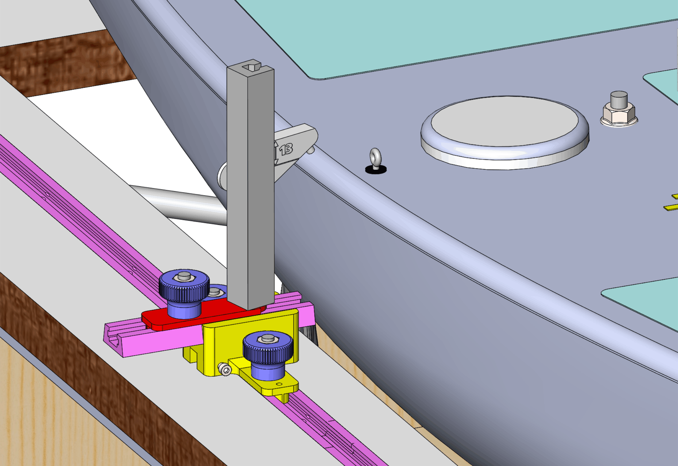
Figure 13. Extreme beam alternative assembly. Deck camberDeck camber is checked using a deck edge indicator which has its upper surface 13 mm above the deck edge, as illustrated in Figure 14.
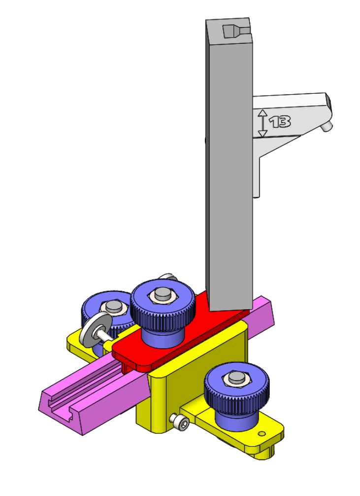
Figure 14. Checking deck camber. The deck camber indicator assembly is shown in more detail in Figure 15. Downloadable STL for deck camber indicator. The indicator in the tower is dropped onto the hull and the deck edge is where the centre of the contact patch touches. The tower may be rotated to improve contact, but as for the tumblehome indicator, if the sheerline is not horizontal in the region of contact, the deck edge point needs to be read on the correct side.
Figure 15. Deck edge and deck camber indicator assembly. Table 1 provides an extract from a workflow document for these steps in 6M measurement.
Table 1. Steps 1 to 5 in 6M measurement workflow.
The next page deals with the Stern station measurements of freeboard, girth, and overhang.
|
|
©2025 Lester Gilbert |