![]()
![]()
![]()
![]()
![]()
![]()
|
|
|
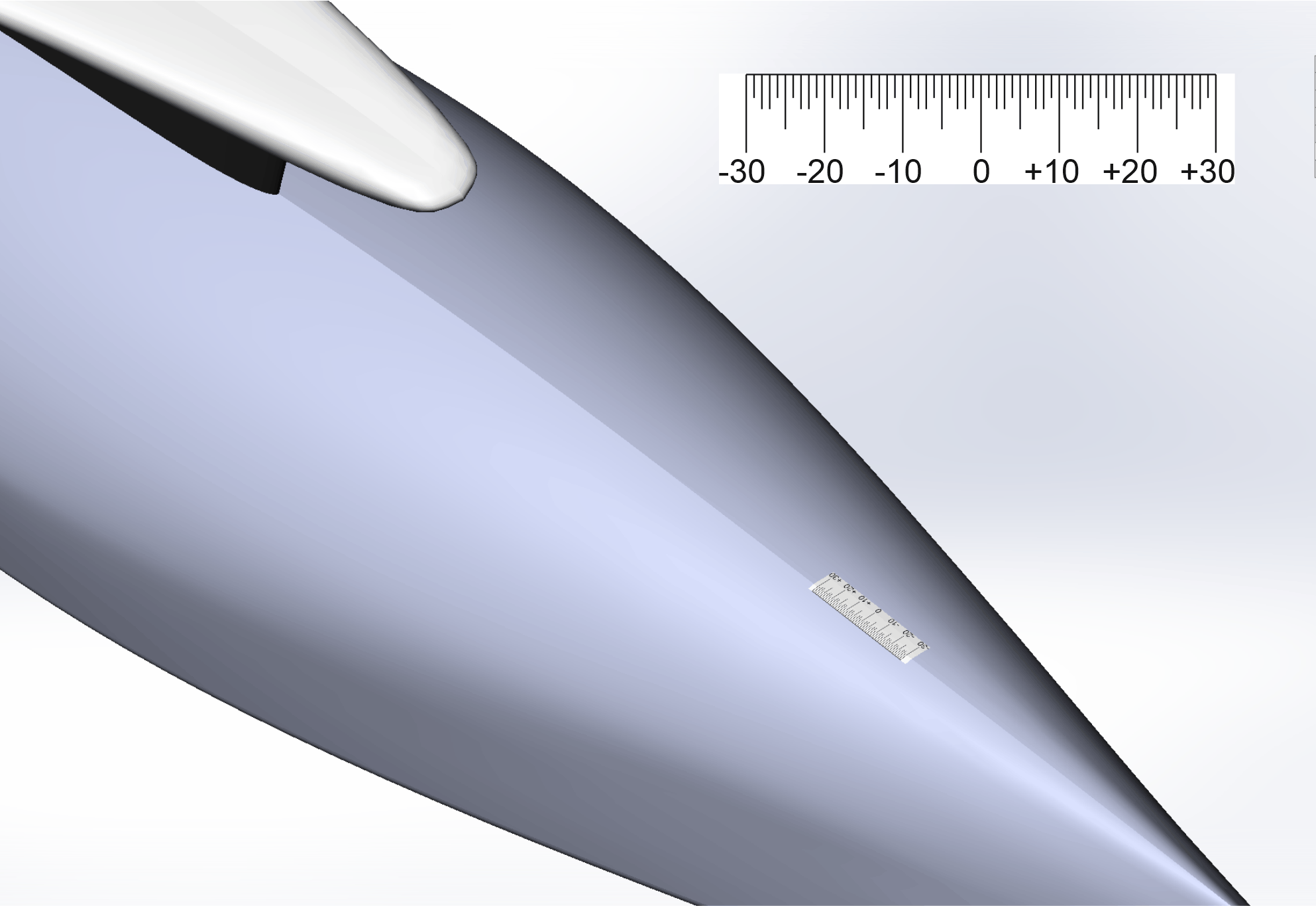
(Previous page in this series dealt with constructing the 6M tank and jig.) The concept for finding the waterline endings of a 6M hull, explained to me by Graham Bantock, is to place an indicator tape on the hull rocker and use a mirror(*) to view the point where the water surface intersects the hull. The point is indicated by a knife edge lying exactly on the water surface and touching the indicator tape. (*) An inspection mirror with an extendible telescopic handle, as might be found in a car accessories store. Figure 1 illustrates a length of self-adhesive indicator tape stuck to the forward rocker of a 6M hull. The tape markings are approximately 1mm apart, but exactness is not required here since they only show a nominal position on the rocker. My tapes are printed using a Brother 9500PC thermal label printer and 18mm tape, but a 10mm strip printed on an Epson or Canon laser or inkjet printer and stuck on with 18mm transparent sellotape would work just as well. An aside on the tape markings, which are a little different from usual ruler markings. They are in a style found on "Starrett" rules which I think does make them easier to read in less than ideal circumstances.
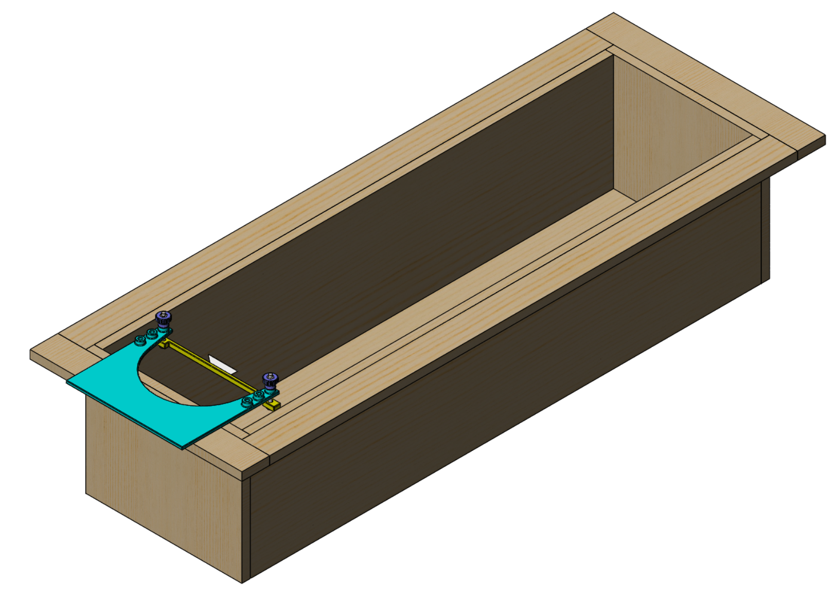
Figure 1. Forward rocker with indicator tape attached. Figure 2 illustrates the equipment deployed to find the waterline ending. A carrier holds the knife edge, simply a blunted Stanley craft knife blade, which is raised or lowered in a frame clamped to the sides of the flotation tank at one end.
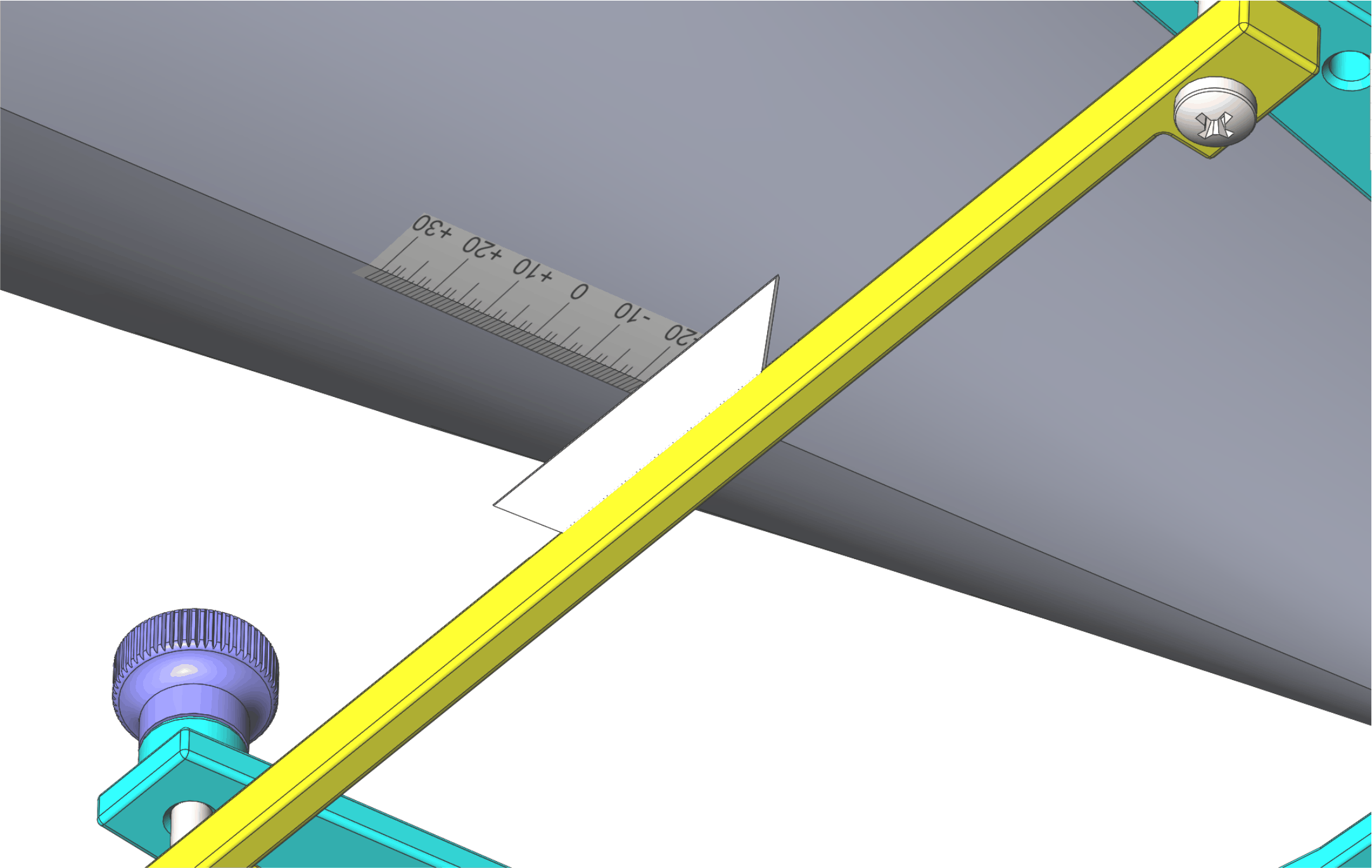
Figure 2. Tank with frame and knife edge carrier. Taking the reading is illustrated in Figure 3, where the knife edge is indicating a value of "-21".
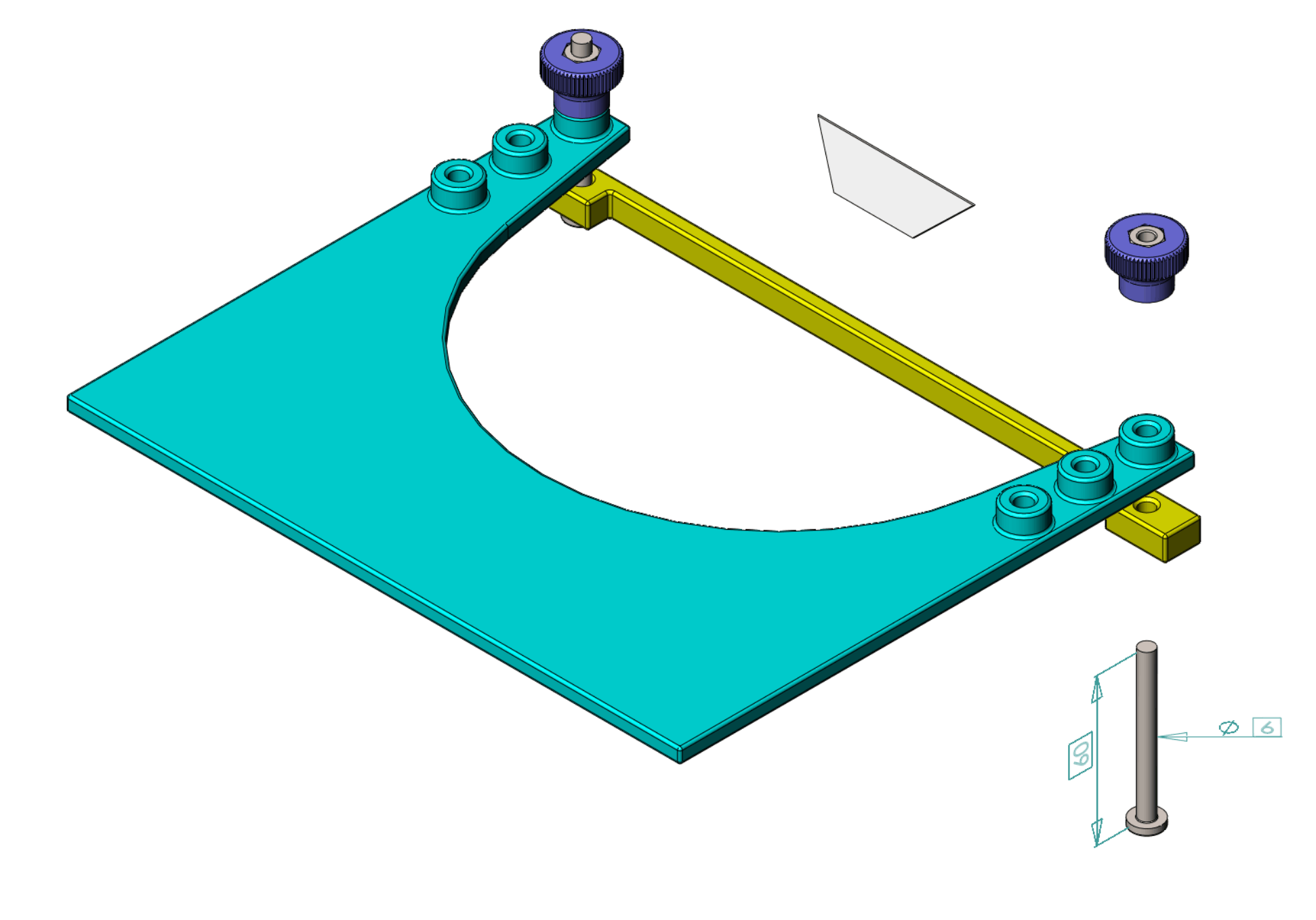
Figure 3. Knife edge indicating "-21" on the tape. Details of the frame, knife carrier, and adjustment screws are shown in Figure 4. The adjustment knob is 3D printed and has a M6 nut pressed in with an interference fit. Download STLs are knob, frame, and carrier30. The "30" is for a carrier the holds the blade at 30° off vertical and is suited to readings where the indicator tape is somewhat horizontal on the hull rocker. Carrier60 holds the blade at 60° and is suited to an indicator tape laid somewhat vertically, typically on the truncated aft bustle of a 6M.
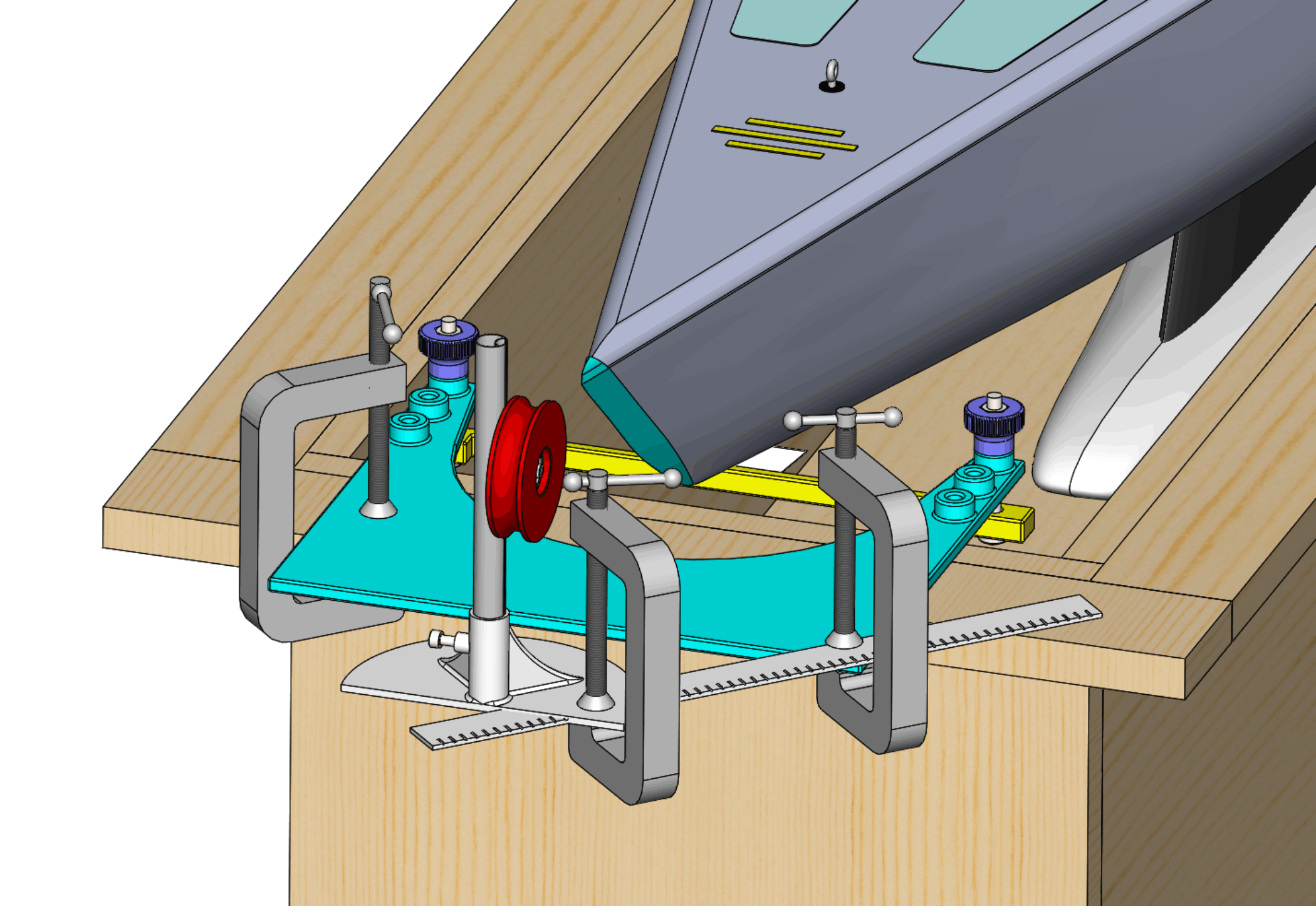
Figure 4. Knife edge frame and carrier. In use, the end of the tank can get a little busy. Some means is required to gently draw the hull towards the knife edge. Pushing the hull in any way doesn't work; it turns out that a M6 nut on a length of thin cotton thread attached to the hull does the job rather well. Figure 5 illustrates a setup where the cotton thread is run over a wheel carried in a stand which is clamped to an extension piece, perhaps a ruler, itself clamped to the end of the tank.
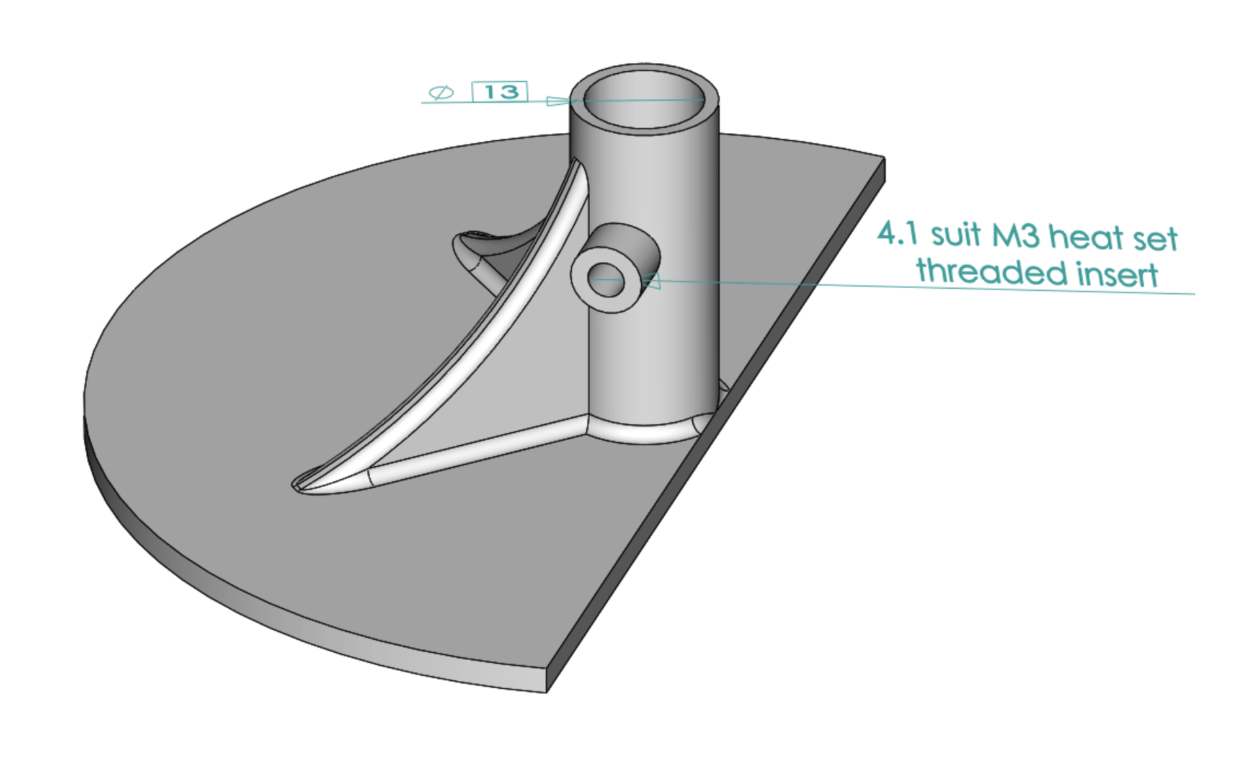
Figure 5. Draw equipment clamped to tank edge. The stand for the draw wheel is illustrated in Figure 6, draw-stand STL for download. It takes a piece of 13mm mast tubing or similar. The M3 screw to clamp the tube in place in the stand is expected to run in a heat set threaded insert, so the opening is sized at 4.1 to suit.
Figure 6. Stand for draw equipment. The next page deals with positioning the hull in the dry measurement jig.
|
|
©2025 Lester Gilbert |