![]()
![]()
![]()
![]()
![]()
![]()
|
|
|
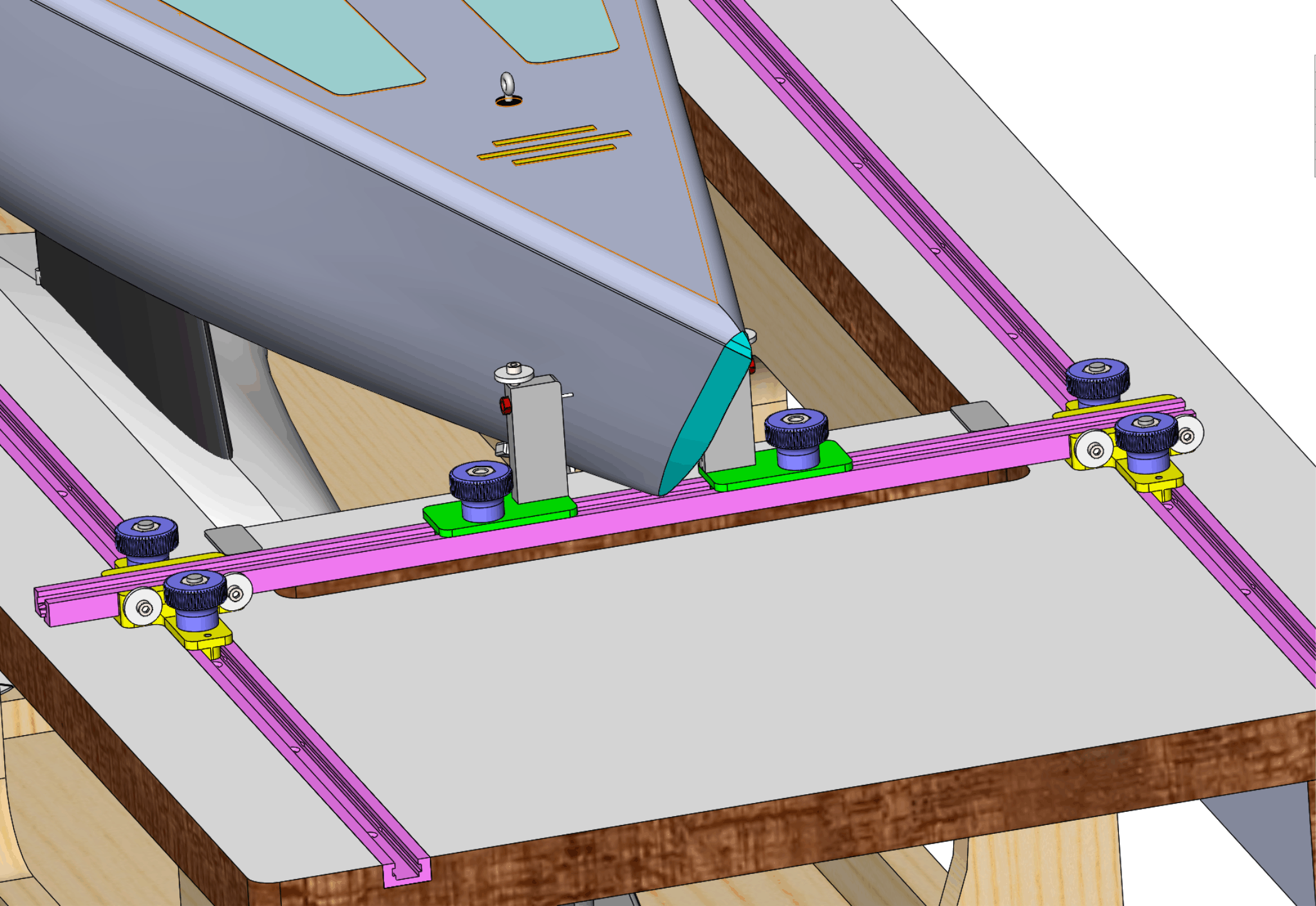
(The previous page dealt with measurements at the Stern stations.) Bow girthThe bow station girth measurement is taken at 42 mm above the water plane, as illustrated in Figure 1. A length of Dyneema line runs through the syringe needle tips and is clamped when pulled against the hull surface, the arrangement previously shown in Figures 4, 5, and 8 of the Stern station measurements page.
Figure 1. Measuring bow girth. The indicators on the cross-track are illustrated in Figure 2.
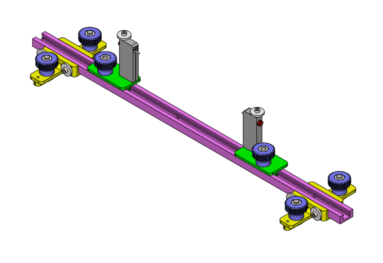
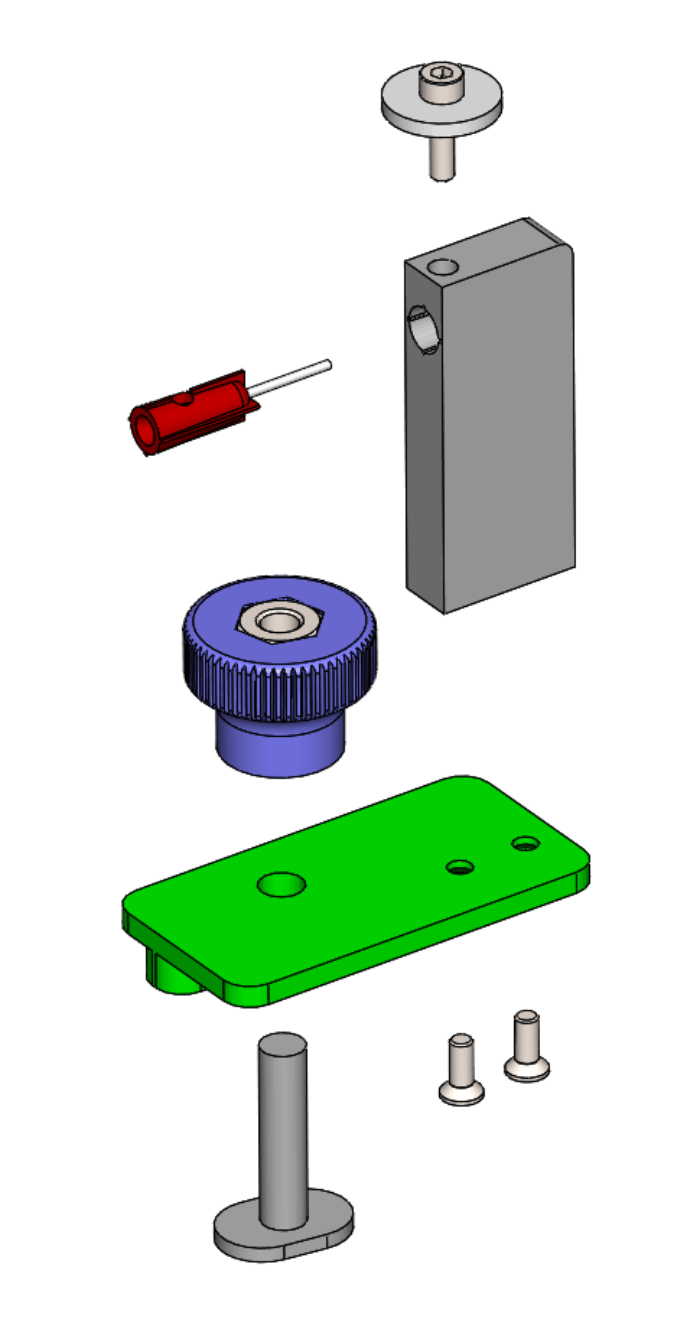
Figure 2. Bow girth measuring equipment. The bow girth indicator positions the syringe needle at the appropriate height. Downloadable STL bow girth indicator. Detail of the indicator assembly is shown in Figure 3. The port and starboard plates are the same as those shown for the stern station equipment.
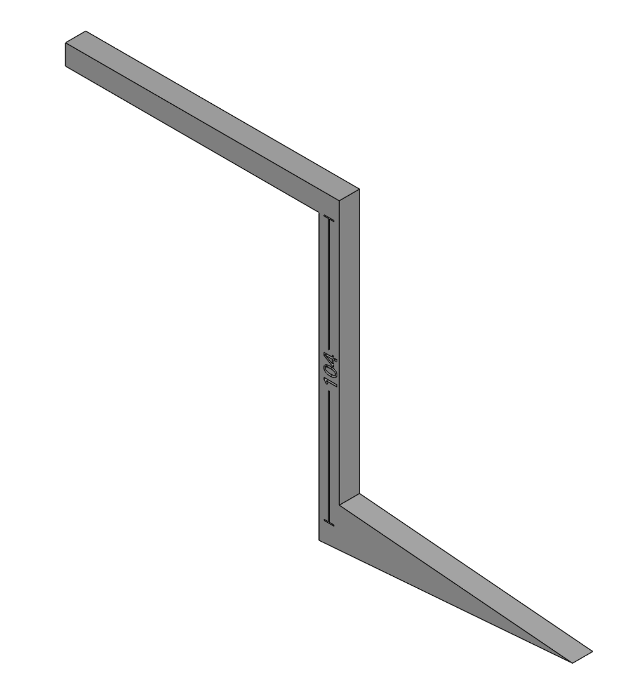
Figure 3. Bow girth indicator assembly. Girth station chain and skin girthGirth at the girth station is measured from the deck edge to 104 mm below the waterplane. If the hull draught is less than 104 mm, the "chain" girth departs from the hull surface and ends at the point on the keel that is 104 mm below the water plane. The "skin" girth follows the entire hull surface and then tracks down the keel until the 104 point. The difference between chain and skin girth enters into the rating formula as a possible tax or penalty. If the hull draught is 104 mm or greater, then skin and chain girths are identical, there is no tax or penalty, and there is consequently no need to carry out the measurements. Figure 4 shows a probe designed to determine if skin and chain girths need to be measured at the girth station. The upper arm is laid on the jig top and the vertical run against the side of the jig. If the lower arm of the probe contacts the canoe body surface there is no need for girth measurement.
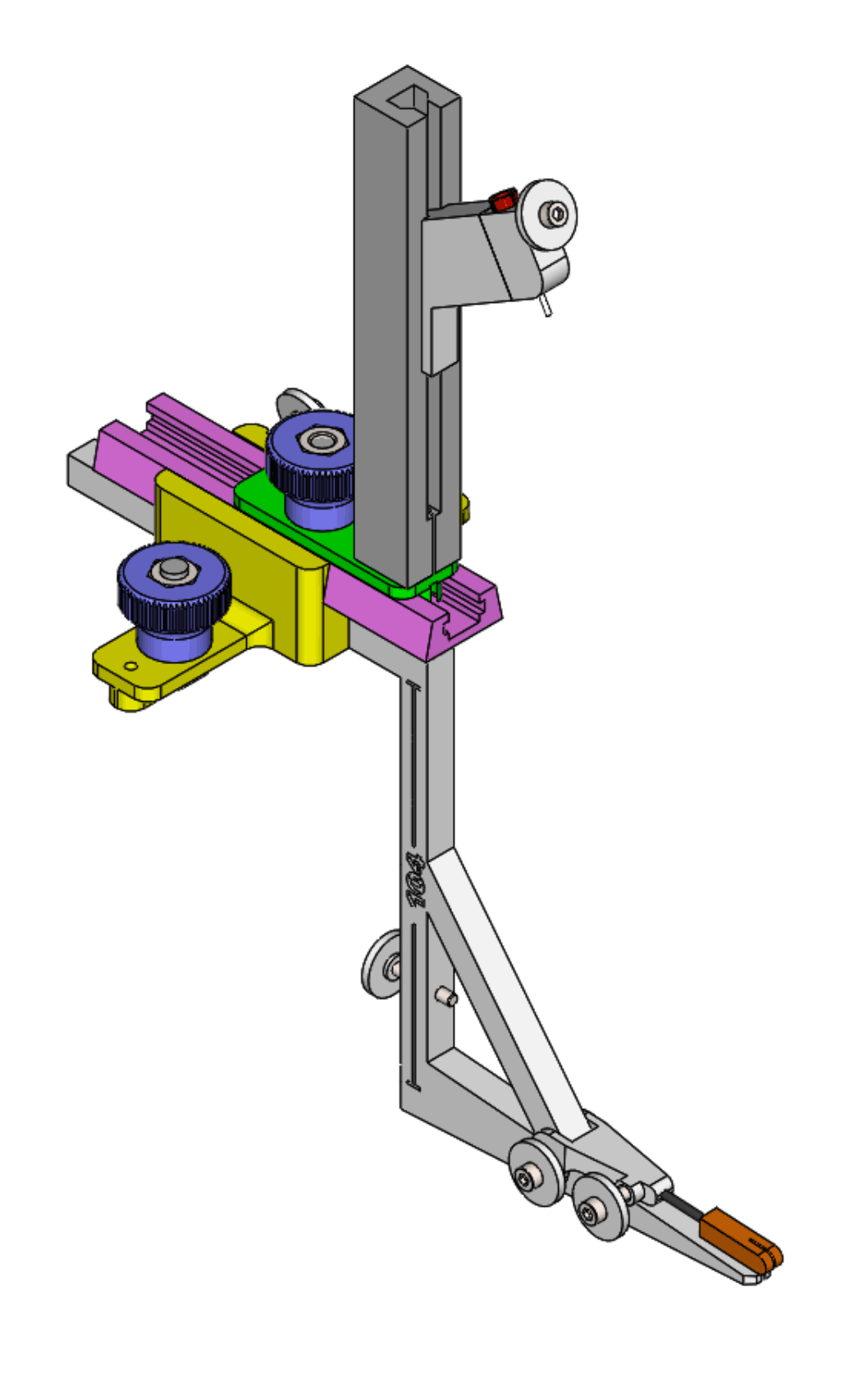
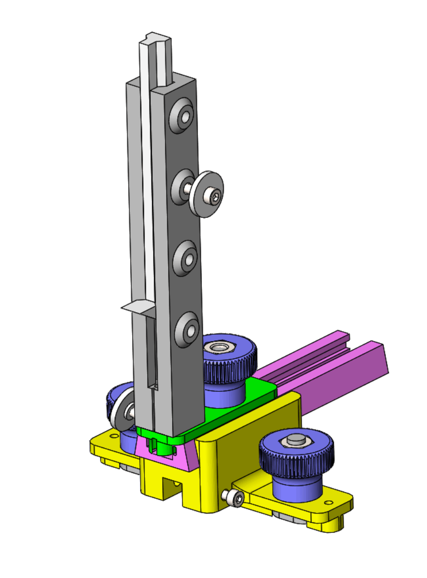
Figure 4. Girth station probe. Figure 5 illustrates the girth station measuring equipment if skin and chain girths need to be measured. The upper components of the girth measuring assembly are the same as those used for the stern station girth measurements. The plate for the tower is not handed, download STL girth station plate.
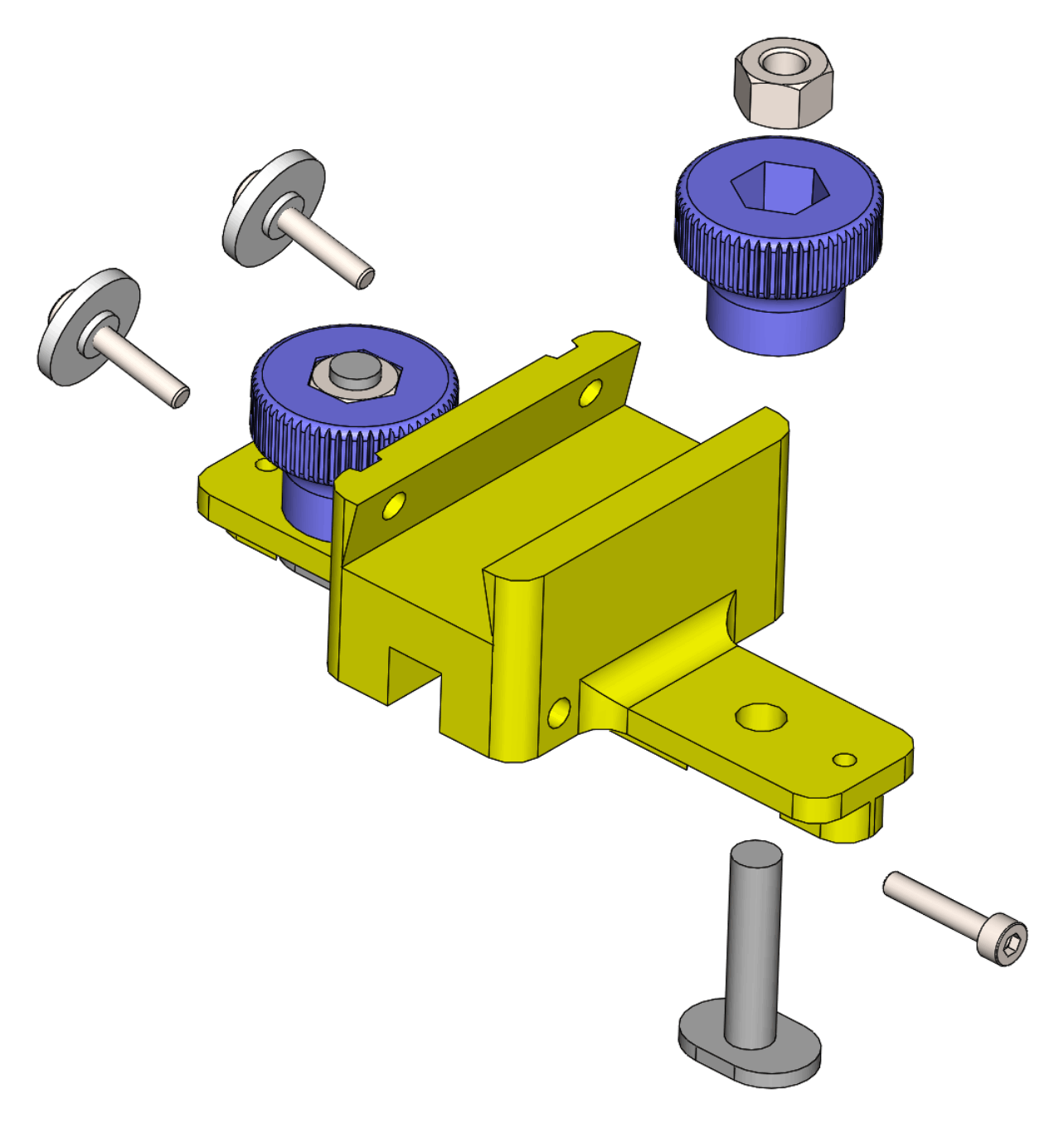
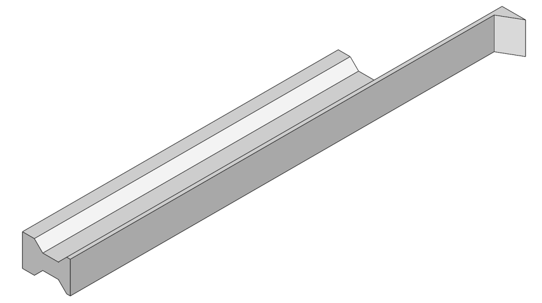
Figure 5. Girth station skin and chain girth assembly. The girth station carrier is shown in Figure 6. It holds a length of dovetail T-track 25 mm above the jig top, and has a channel for the upper arm of the lower girth measurement component to be clamped in place.
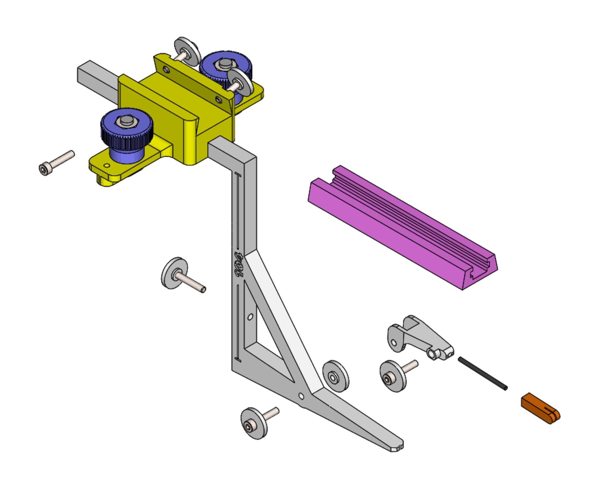
Figure 6. Girth station dovetail T-track carrier. The lower components of the girth measuring assembly is shown in Figure 7. The lower arm of the indicator has a notched tip so that it holds the knotted end of the Dyneema girth line against the keel. The fork on the lower arm carries a notched nose that can be angled as needed to hold the girth line at the join between keel and hull for skin girth measurement. The nose can be extended or retracted in the fork to accommodate keel thickness, and retracted or removed for chain girth measurement. The nose is mounted on a length of 2 mm diameter aluminium rod, otherwise known as a knitting needle.
Figure 7. Girth station lower girth indicator detail.
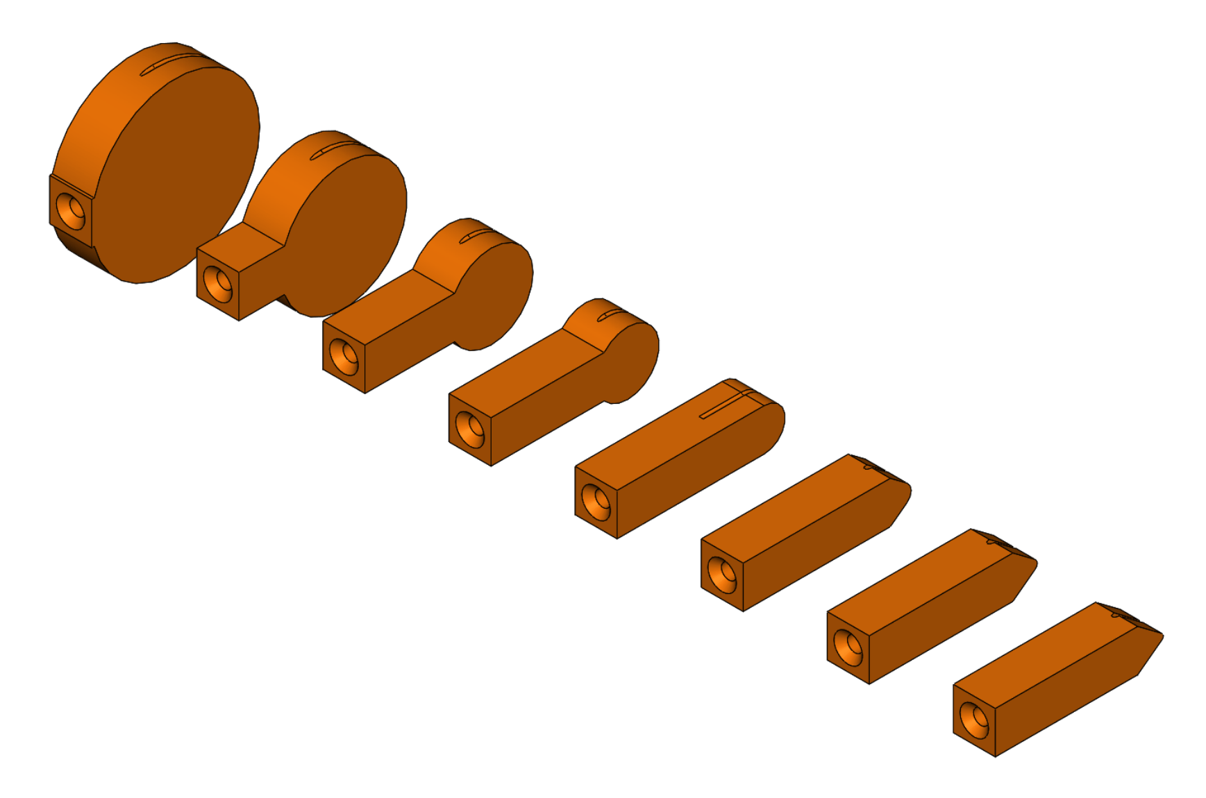
A variety of fork nose profiles are provided as shown in Figure 8.
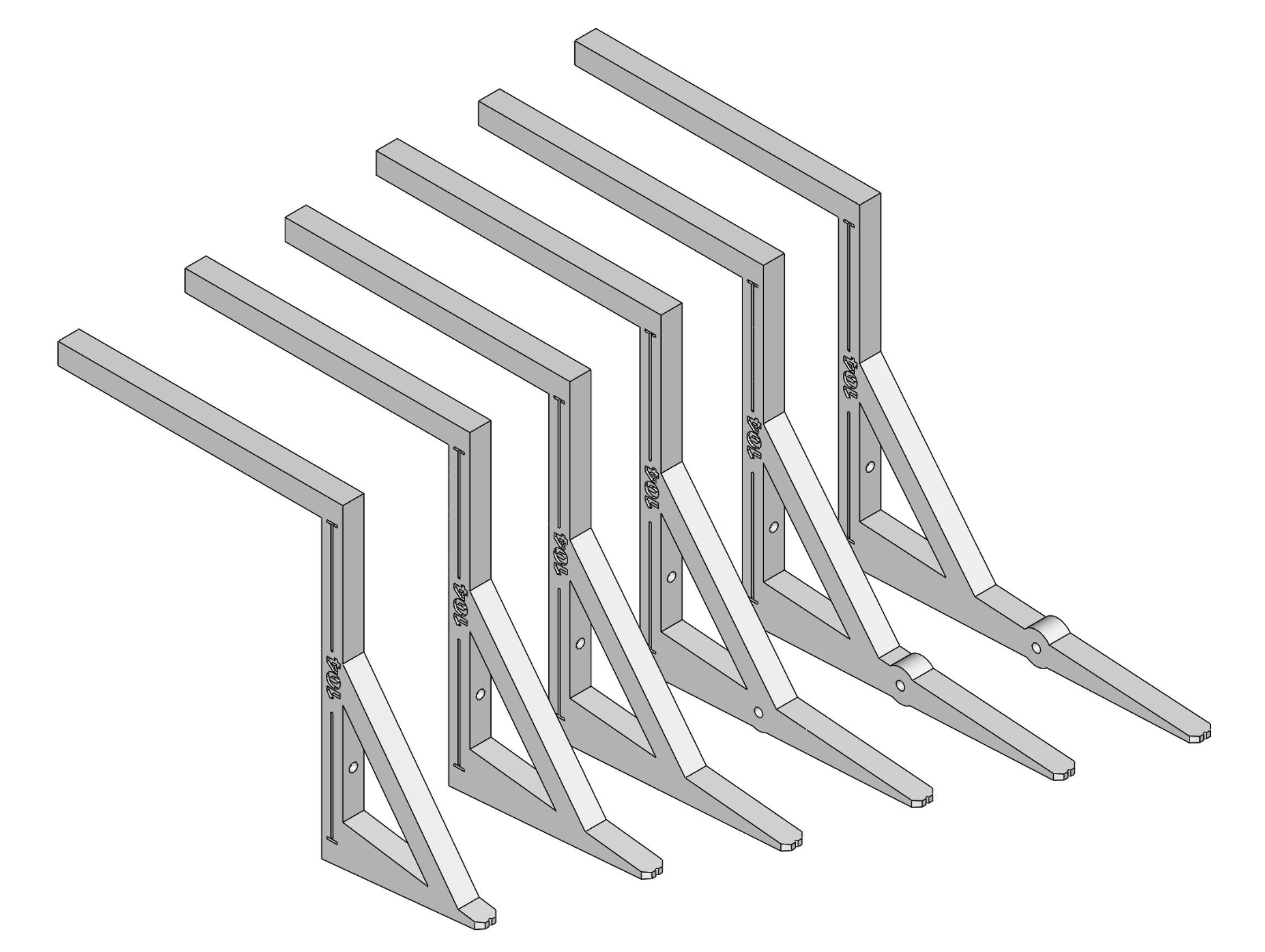
Figure 8. Fork noses. Downloadable STLs for probe, dovetail carrier, fork, nose20, nose15, nose10, nose7.5, nose5, nose2.5, nose1.3, nose0.8. The carrier and fork STLs make provision for M3 heat set inserts at the places where thumbwheels clamp items in place. Girth station maximum beamThe girth station "maximum beam" is measured at 104 below the waterplane (or lower if the maximum occurs lower*). Note that this is not the same beam as is measured as the girth station "beam" which is measured at 33.3% of freeboard above the waterplane. Depending up the particular 6M design, displacement, draft, etc, a variety of lower girth indicator sizes may be needed, as shown in Figure 9, to place a measurement point at 104 below. The upper arm of the indicator is placed on the jig top and moved laterally to contact the hull or keel. The lower arm is a defined length, allowing measurement of the beam from the jig side. (*) A lower beam would typically be measured at the ballast if it is particularly flattened or has wings.
Figure 9. Indicator sizes. Downloadable STLs for indicator104-135, indicator104-120, indicator104-105, indicator104-90, indicator104-75, indicator104-60. The STLs make provision for M3 heat set inserts at the places where thumbwheels clamp items in place or brace the vertical part of the indicator against the jig side. Girth station beamThe beam at the girth station is measured at 33.3% of the freeboard above the waterplane. Depending upon the tumblehome, the position of this beam measurement point might be below the position of maximum beam. In this case, a special indicator is needed to allow measurement. The required indicator assembly is shown in Figure 10 and the indicator itself in Figure 11.
Figure 10. Girth station beam measurement assembly. The indicator projects 5 mm, as illustrated in Figure 11, to reach the girth station beam if it lies below the hull maximum beam.
Figure 11. Girth station beam measurement indicator. Downloadable STL girth beam 5. An extract from the workflow document for the bow and girth station measurements is shown in Table 1.
Table 1. Bow and girth station measurement workflow. The measurements may be entered into the MYA spreadsheet and estimates made of A, B, I, and J for sails. Further measurement checks are probably best done after the sails have been made. The list is given in Table 2.
Table 2. Remaining measurement workflow.
|
|
©2025 Lester Gilbert |