![]()
![]()
![]()
![]()
![]()
![]()
|
|
|
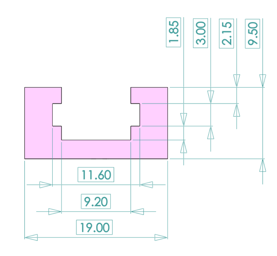
(Previous page dealt with preliminary 6M measurements in the dry jig.) The stern station measurements are done 13 mm above the water plane for station 1, and 25 mm for station 2. Accordingly, the cross-track carriers used at stern station 1 place the upper surface of the cross-bar T-track 13 mm above the jig top, and the station 2 carriers at 25 mm above. The dimensional specifications of the T-track, supplied by Axminster (*), are given in Figure 1. The various 3D STL files for carriers and plates assume these dimensions and will not work with T-tracks of different dimensions. (*) Axminster supplies a number of T tracks of varying specification. This is their general purpose "jig" track.
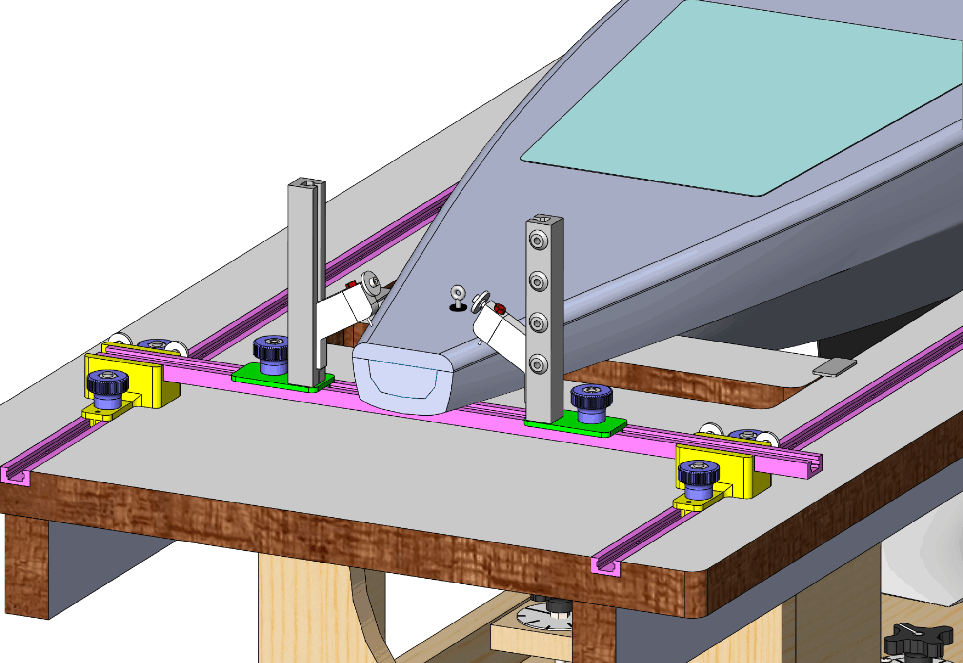
Figure 1. T-track dimensions to suit 3D STL files for carriers and plates. FreeboardFigure 2 illustrates measuring freeboard at stern station 1. Towers carry deck edge indicators with freeboard distance marks. The towers are set on port-hand and starboard-hand plates which align the indicators with the relevant edge of the cross track. The cross track is set at 13 mm high using "Carrier 13" assemblies and is moved so that it just touches the hull profile, thus establishing the position of stern station 1.
Figure 2. Measuring freeboard. The details of the freeboard equipment are shown in Figure 3. The deck edge indicator is different from the one used to check deck camber. In particular, its contact "patch" is the needle of a syringe tip, 1.8 mm Ø, and accurately identifies the deck edge for any sweep of the sheerline.
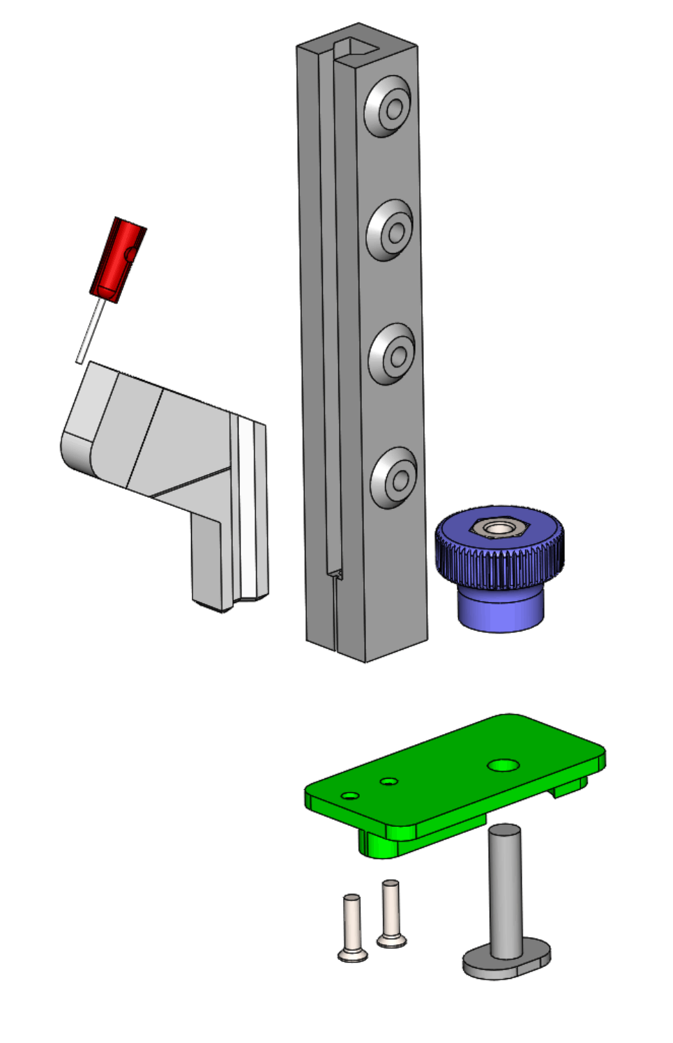
Figure 3. Freeboard measurement assembly. The deck edge indicator carries a standard hypodermic syringe tip angled at 30° with a 1.8 mm Ø "needle", of the kind used to dispense hobbyist glue or colouring liquids. The needle projects exactly 7 mm from the indicator, coinciding with the indicator's horizontal line used as a reference mark for measurement to the position of the deck edge. The plate illustrated is for the starboard side of the station where it offsets the tower appropriately. Downloadable STLs for freeboard deck edge indicator, tower, starboard plate, port plate. Girth at a stern stationFigure 4 illustrates girth measurement at stern station 1.
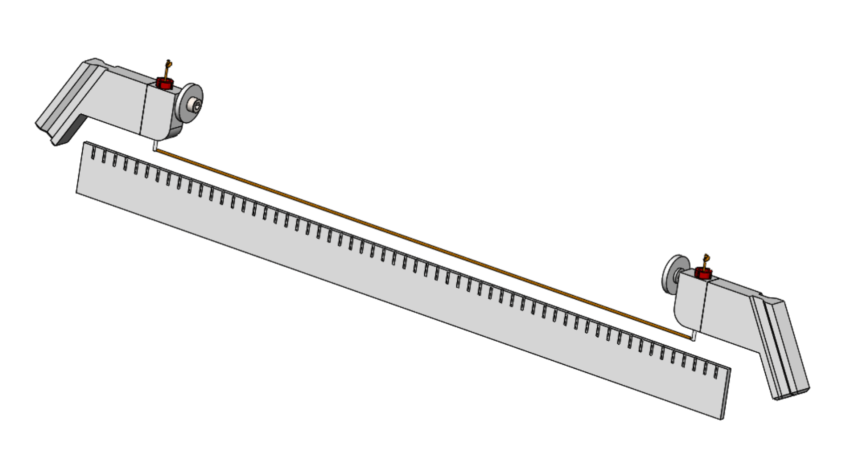
Figure 4. Measuring girth at stern station 1. Here, the deck edge indicators carry a Dyneema (*) line through the syringe tips whose length is locked after being drawn around the hull. The cross-track is then moved aft, and the indicators removed to allow the measurement of the length of the line, as shown in Figure 5.
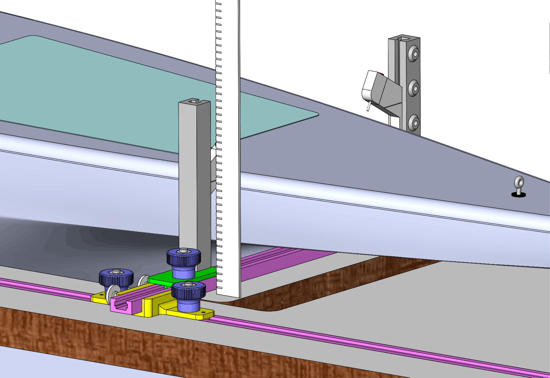
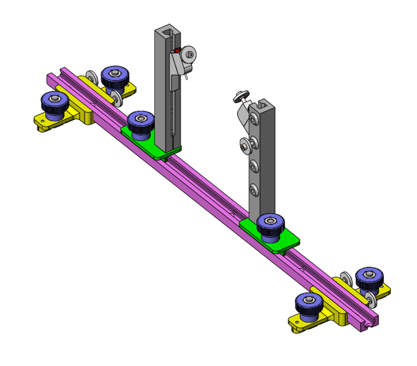
Figure 5. Girth measured against ruler. Detail of the girth indicator cross-track assembly is shown in Figure 6, and the girth indicator itself is shown in Figure 7. The opening in the indicator for the M2.5 thumbscrew is sized in the STL for a heat set threaded insert (**). Download STL girth indicator. (*) Negligible stretch under light load.
Figure 6. Cross-track assembly for measuring girth at stern station 1.
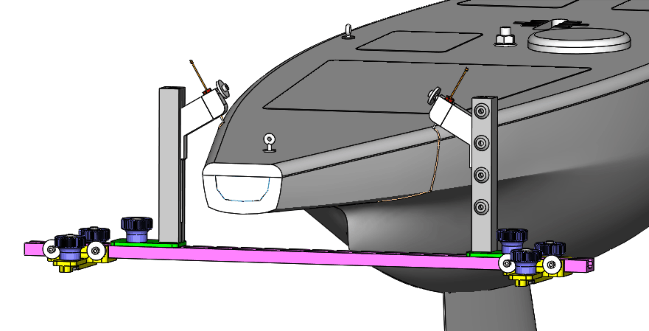
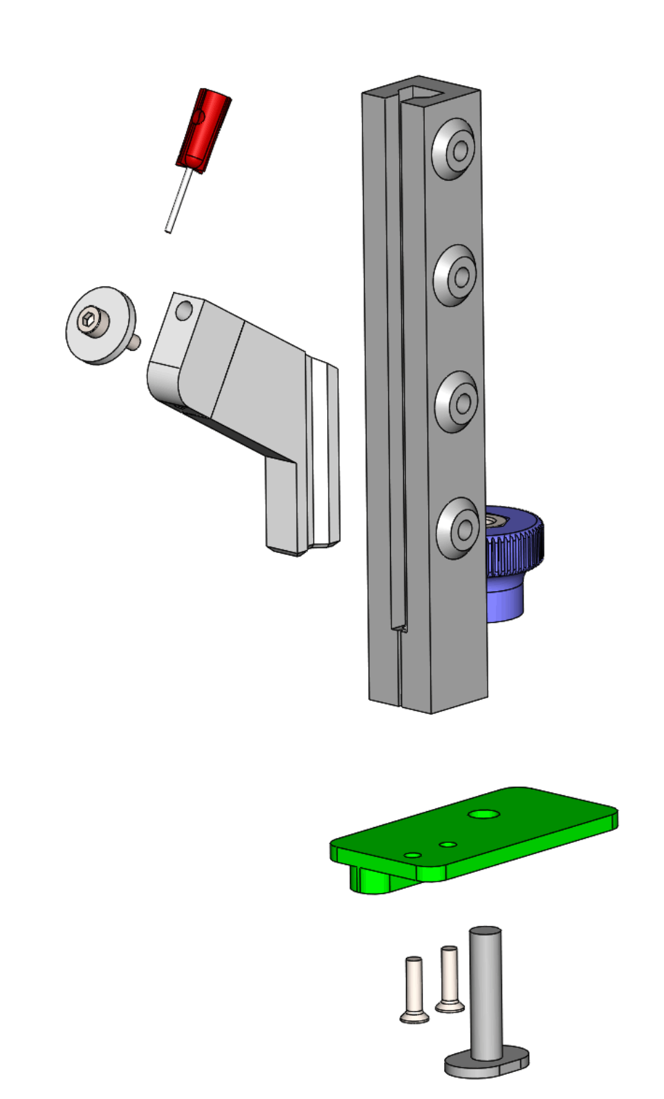
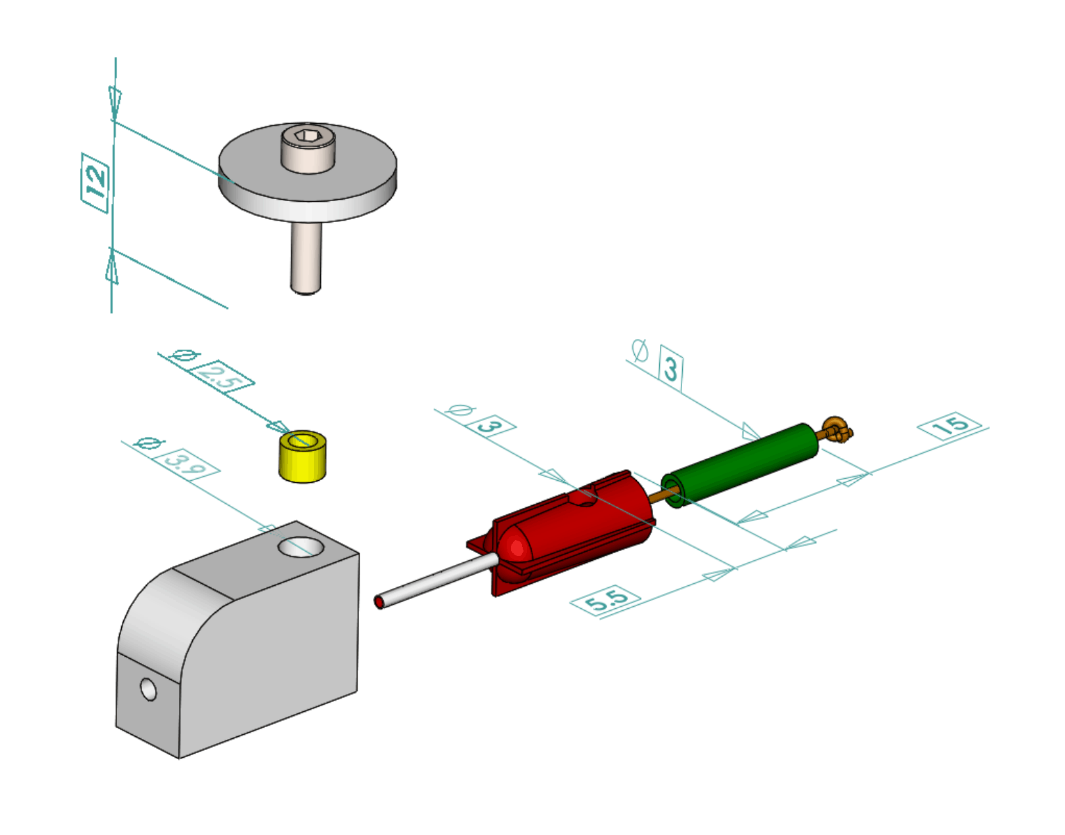
Figure 7. Girth indicator and assembly, port side, at stern station 1. Figure 8 provides more detail of the girth measurement line layout at the syringe tip needle. A 15 mm length of 3 mm Ø silicone tube is inserted into the syringe tip to provide a cushion for the Dyneema line. The syringe tip has a 3 mm Ø opening drilled in its body, 5.5 mm from the syringe end. The opening allows the M2.5 x 12 mm clamp thumb screw to pass through the body and clamp the line within its silicone tube protection. The indicator provides a 3.9 mm Ø opening for a M2.5 brass threaded heat set insert to suit the thumb screw.
Figure 8. Syringe tip layout. Arrangements for stern station 2 are the same, except the cross-track uses "carrier 25". Download STL carrier 25. Figure 9 illustrates girth measurement at stern station 2.
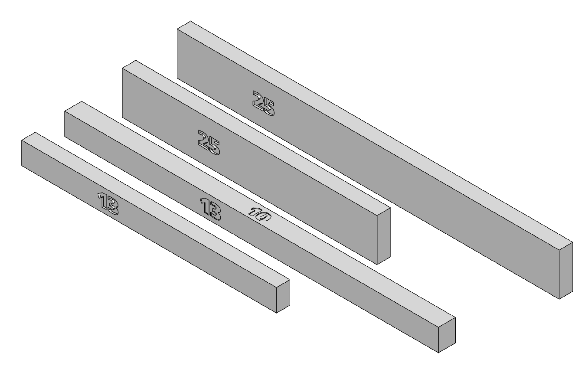
Figure 9. Measuring girth at stern station 2. It may be convenient to have indicator blocks that are 13 mm and 25 mm high, usually for measuring the distance between stern stations 1 and 2 and possibly for station extension. These are illustrated in Figure 10, downloadable STLs 13 block, long 13 block, 25 block, long 25 block. They are 8 mm thick, while the long 13 is 10 mm thick for some reason.
Figure 10. Height blocks. Table 1 provides the workflow steps for the stern station measurements.
Table 1. Workflow of stern station 1 and 2 measurements. The next page deals with measurement at the Bow and girth stations.
|
|
©2025 Lester Gilbert |