![]()
![]()
![]()
![]()
![]()
![]()
|
|
|
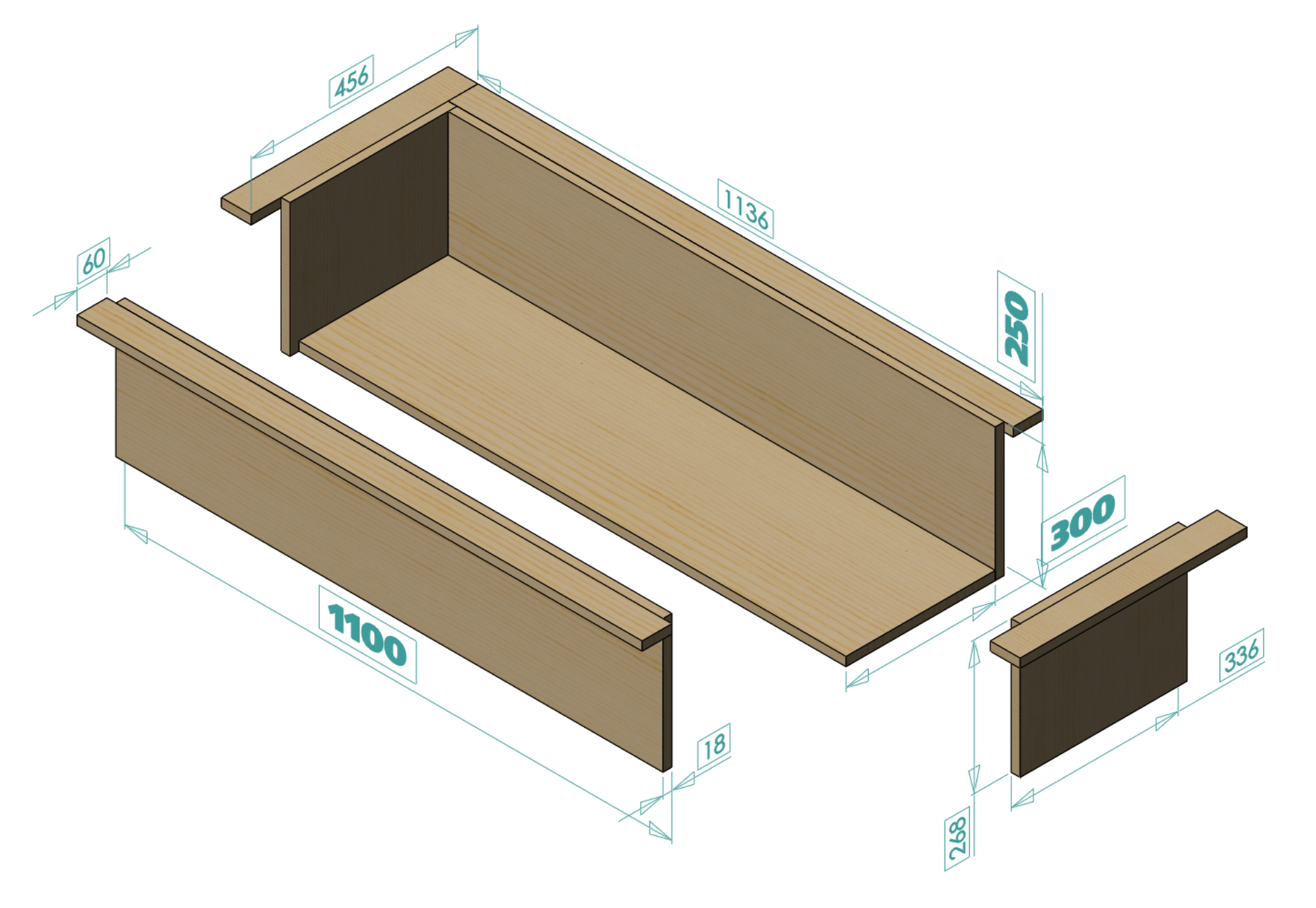
When it came time to have my 6M certificated, I found there were only a small number of 6M Official Class Measurers in the UK. One of the issues is the difficulty in constructing the various items of equipment needed to measure water endings, freeboard, girth, beam, and so on. I decided to see what 3D printing might offer. First, though, was building the two bulky items conventionally: a flotation tank, and a dry measurement jig. Flotation tankI first tried to locate an indoor aquarium tank that might be large enough. Getting a quote for a new build was relatively straightforward, but the prices were beyond my pocket. I then looked at second-hand tanks, but few matched the dimensions I wanted, and those that did turned out to have some problems on inspection. So, I built one out of 18mm ply as illustrated in Figure 1. Graham Bantock waterproofed it with a layer of light weight glass fibre mat and epoxy. Alternative approaches include a lining of carefully folded thick plastic sheet or tarpaulin.
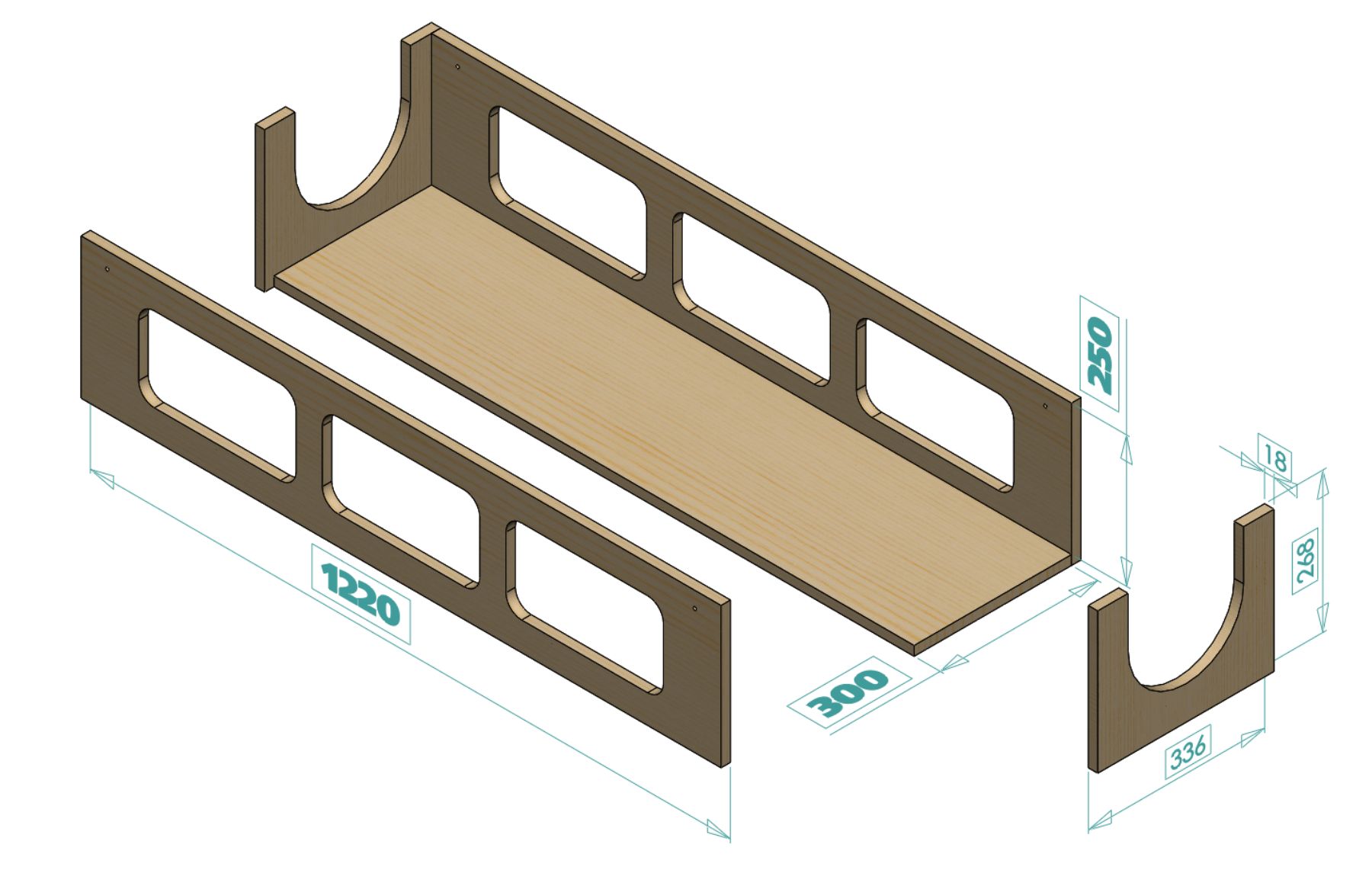
Figure 1. Flotation tank. Dimensions in mm. If I were to build this again, I would make it a little longer. Depth and width were fine once filled to the brim with water and a floating boat, but length was a little cramped, 1200 would be better. Dry measurement jigThe base was built from 18mm MDF, shown in Figure 2.
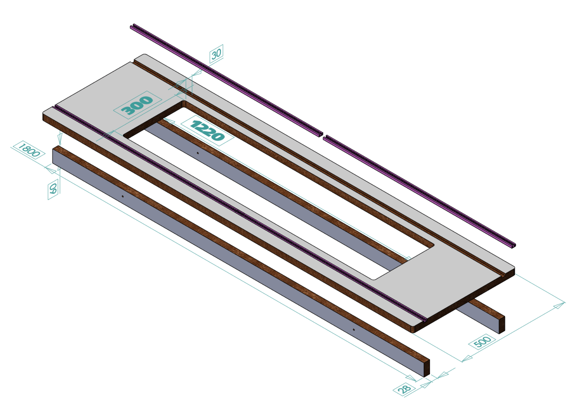
Figure 2. Dry measurement jig base. Dimensions in mm. An opening was cut into a 28mm kitchen counter top to make the jig's working surface, as illustrated in Figure 3. A channel was routed on each side of the opening to take lengths of T-track.
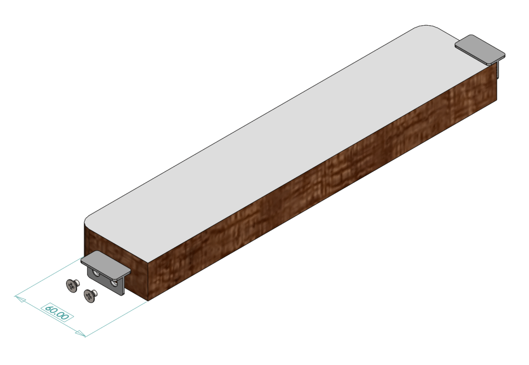
Figure 3. Dry measurement jig top. Dimensions in mm. The off-cut from the table top opening was used to make some inserts (one each of 40, 60, 80, and 100 mm long) that are needed to properly position the boat in the jig. A length of "T" aluminium extrusion was attached to each side of the insert, as shown in Figure 4, to hold the insert in the opening at the same level as the jig top.
Figure 4. Insert for jig top. Dimensions in mm. If I were to build the dry jig again, I would also make it a little larger. Depth was fine, and the opening would be a little longer to match the longer tank by 100 to go to 1320, but now the width was definitely cramped, at least an extra 50 each side would be better to give 400. The base and top, ready to be mated, are illustrated in Figure 5. A hole can be seen in each corner to take an M6 bolt to keep them mated while sat on the work bench.
Figure 5. Dry measurement jig. Draft plateThe final item for conventional construction was the draft plate which sits inside the jig. It was made from 18mm MDF. Its dimensions and construction are illustrated in Figure 6.
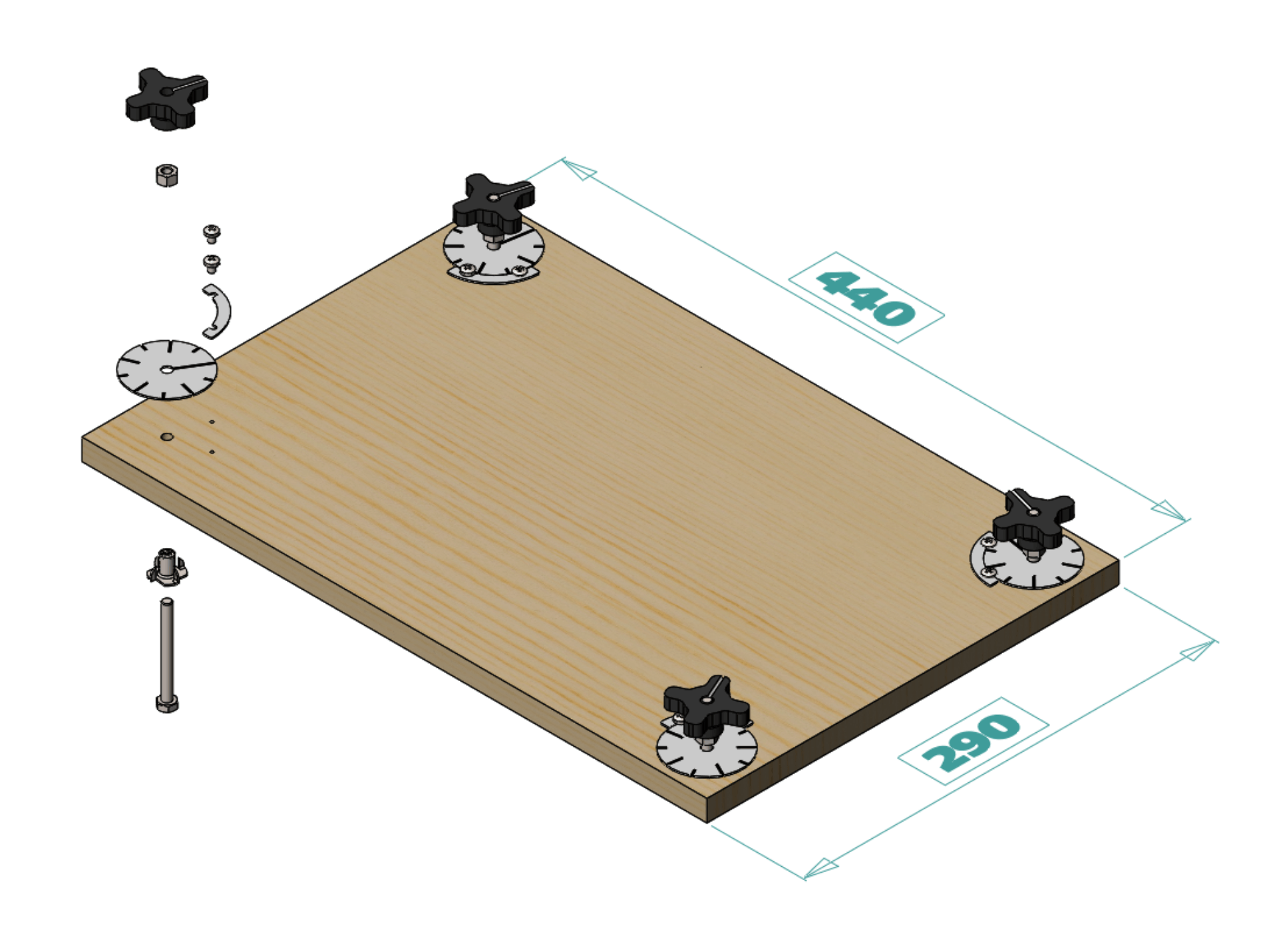
Figure 6. Draft plate. Dimensions in mm. The 4-star hand wheel was out of my bin of parts, but it could as well be 3D printed. The hand wheel bolt was M6, so a full turn of the adjuster lifted or dropped the plate 1mm. The indexing dial allowed a drop or rise of 0.1mm. The bolt heads were trued in a lathe and then the edges ground smooth to avoid damaging the jig base.
Figure 7. Dial and spacer. The indexing dials and crescent spacers for the clamping screws were 3D printed as shown in Figure 7. Download STLs for dial, spacer. The plate was set horizontal in the jig, the dials then turned to match the position of their hand wheels and clamped in position with pan head screws and crescent spacers. Next page for finding the waterline endings.
|
|
©2025 Lester Gilbert |