Earl Boebert mentioned Turner's metacentric shelf theory on Chad's RC Sailing
forum, and wondered if anyone could provide a spreadsheet to do some of the
calculations. I've wanted an excuse to study Turner for a while, so added
some code to the spreadsheet for hull design using circular arcs (Design/Balance/Designv30.xls),
original on the Hull design with arcs page,
to show the graph plots that Earl mentioned. (Earl's interesting post is
reproduced below by permission.)
The first graph is for a hull with a wide transom, and sure enough it shows a
lack of balance according to Turner's theory.
The second graph is for a hull with a very modest transom, and here we see it is
almost perfectly balanced according to the theory.
The stability calculation performed by packages such as Hullform, which
compares the heeled and upright centers of buoyancy, is correct but
insufficient to produce a truly balanced hull. I learned this to my dismay
when I designed and built a free sailing boat balanced according to this
criteria alone. It was a disaster.
Digger deeper into the topic of balance I inevitably encountered the
metacentric shelf notions of Admiral Turner. His methods are the subject of
some controversy in Naval Architecture, not the least because he developed
them first as a model yachtsman and only later applied them to full-sized
boats. Perhaps the most even-handed treatment is by CA Marchaj in his book
"Seaworthiness:"
"The main criticism directed against Turner's concept of the metacentric
shelf as the sole criterion of balance is that for convenience it involves
only hydrostatics ...
"Nevertheless, to quote K.C. Barnaby's comment expressed during a
discussion of Turner's paper, 'we may doubt the accuracy of some of his
reasoning, but the fact remains that boats balanced on his metacentric shelf
principle to turn out to be uncannily steady in their course.' In practice,
Turner's theory has proved remarkably reliable in predicting yacht behaviour
from lines plan, so the error introduced by [hydrodynamics] cannot be
serious."
(As an aside, sorting out the relation between the the static and dynamic
effects would make a decent thesis topic for an aspiring graduate student.)
The description that follows is not, strictly speaking, what Turner
called the "metacentric shelf", but it is the more interesting of his ideas.

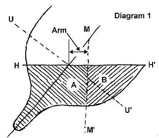
Looking at diagram 1, for a given section U-U' is the upright waterline,
H-H' is the heeled waterline, A and B are the immersed areas and M-M' is the
heeled metacenter. This line marks the point at which the upward force of
the water is concentrated. The amount of that force is equal to the combined
areas A+B.

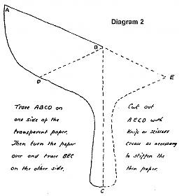
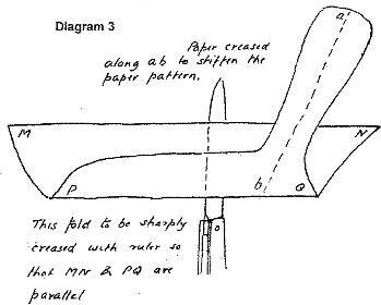
The location of M-M' is found by fiddling around with pieces of paper as
shown in diagrams 2 and 3; the line M-M' is where the folded section shape
balances on a knife edge. The degree of heel being analyzed is usually
chosen to be "rail down."

Once we have located M-M' for a particular section we can measure the
offset, or "arm" that the upward force of buoyancy exerts away from the
center line of the boat, as shown in diagram 1. Multiplying this by the area
A+B (measured by counting grid squares, or with a planimeter) gives a
"moment," or force exerted at a distance.
We can then plot the moments along the centerline of a the boat by doing
the (tedious) job of finding the arm and area at each section, multiplying
them, and plotting the result on a horizontal line. If M-M' is to the right
of the center line we plot it above and if it is to the left we plot it
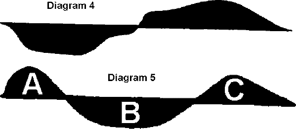
below. Connecting the resulting points gives us curves such as in diagram 4
and 5.

Diagram 4 is a curve for a badly unbalanced
hull, in which, upon heeling, the moments of the forebody move to one side
of the center line and the moments of the afterbody move to the other. The
result is a yaw, or at worse a yaw and a dive at the same time. The
particular curve shown is that for the big Victorian cutter "Satanita,"
which was so hard to handle that in one race she ran out of control and
rammed and sank a competitor. Note that since the two areas are of about the
same size, this hull would be "balanced" under the looser criteria of CB
movement under heel. A similar curve is exhibited by L. Francis Herreshoff's
J boat "Whirlwind," which was notorious for its poor handling
characteristics.
Diagram 5 shows the curve for a balanced hull. The moments for the
forebody and afterbody are on the same side and the moments for the center
of the hull are on the other. The ideal situation is when area A in the
diagram equals area B, and area C equals A plus B.
It is not necessary to go through the whole hoopla to see if a design has
a chance of being balanced. Simply locating M-M' for two sections, one at
about 25% LOA and one at about 75%, will give you a first-cut result. If
both M-M' lines are on the same side of the center line you've got a chance.
If one is on one side and one on the other you're in trouble. From then on
it's trial and error and a wastebasket full of paper scraps. It sure would
be nice if somebody would provide a program that would calculate the moment
of a heeled section from a table of offsets :-)
Since Turner's ideas were championed by cruising yacht designers such as
A.A. Symonds and Harrison Butler, there is a general notion that Turner's
system inevitably produces tubby little double-enders. This is emphatically
not the case. Diagram 5, in fact, is the curve for the schooner "America,"
long lines, hollow entry and all. "America"'s balance was the result of
trial and error in the intensely competitive environment of the New York
pilot schooners. These boats raced each other for jobs through a crowded
harbor, and were often sailed short-handed. They had to be both fast and
handy.
In the model yachting domain, Ted Houk's magnificent M Class design "Rip
Tide" http://www.swcp.com/usvmyg/mclass/riptide.gif is perfectly balanced by
the criteria given above. This was intentional, as I verified by
corresponding with Houk's son. "Rip Tide" was designed in 1949, the design
made the transition from free sailing to radio, and versions were still
winning races and championships as late as the middle 1970's.
It is worth noting that a balanced curve of moments is independent of
both scale and section spacing; it's the form, not the values, of the curve
that counts. This means that you can take a balanced hull that was designed
to one rating rule and adapt it to another without losing its balanced
characteristics. I did this for the boat in the photograph, which is a "Rip
Tide" modified to fit the 36 inch Restricted rules. She tracks through gusts
like she was on rails.
Similar adaptations could be made to convert some of the classic (and
classically well-behaved) M Class free-sailing designs to the IOM rules. Of
course, to do so and claim the design as original would be the height of bad
form. It would still be interesting to see how such boats would do against
some of the "wedge" designs popular lately, especially in difficult venues.
