|
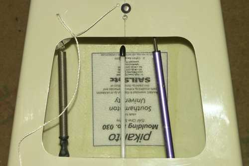
I had the chance to photograph a current production Pikanto from Graham Bantock. These
are some pictures and details of the boat.
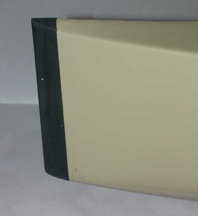 Bow bumper. Bow bumper.
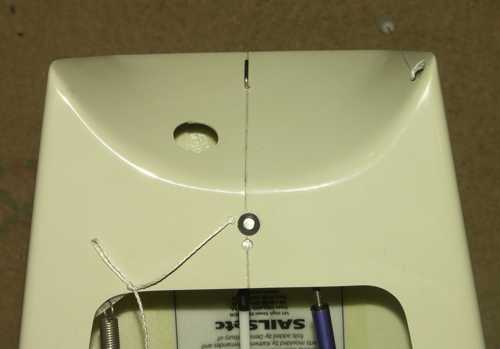
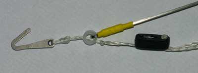
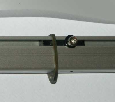
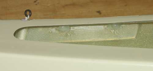 The foredeck
from the side. The No.1 jib pivot attachment line has the small steel ring.
The dabs of silicone sealant show where the pivot pins lie for the No.2 and No.3
rigs. The foredeck
from the side. The No.1 jib pivot attachment line has the small steel ring.
The dabs of silicone sealant show where the pivot pins lie for the No.2 and No.3
rigs.
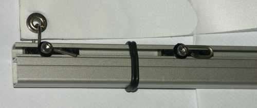
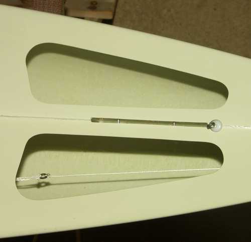 The foredeck
from above. The two pins in the recess are for No.2 and No.3 jib pivots. The foredeck
from above. The two pins in the recess are for No.2 and No.3 jib pivots.
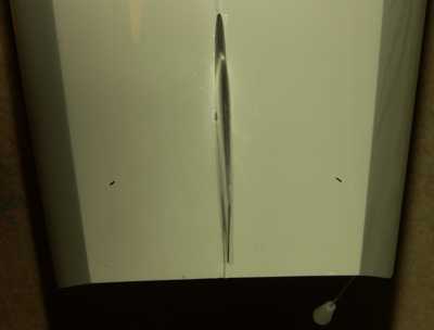
 The
foredeck in front of the mast from the side. The jib sheet exits to deck
level. The
foredeck in front of the mast from the side. The jib sheet exits to deck
level.
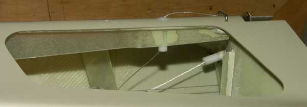
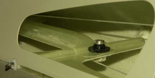
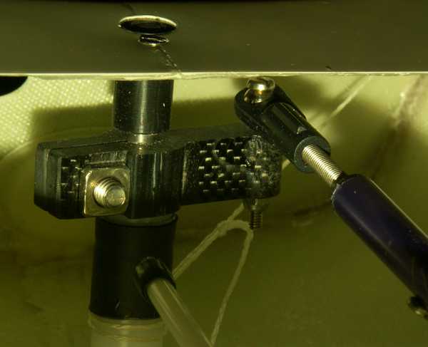
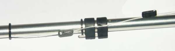
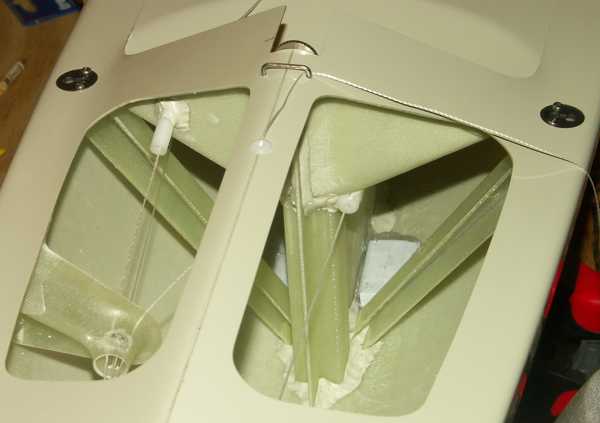 Internal
detail of the bracing around the fin box, and the line runs. Internal
detail of the bracing around the fin box, and the line runs.
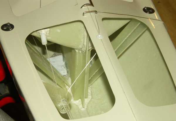
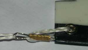
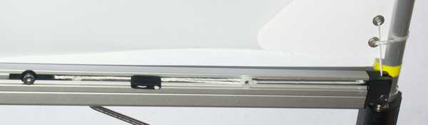
 Detail of the
line guide (part 67g), showing the two pins inserted to keep the three runs separate. Detail of the
line guide (part 67g), showing the two pins inserted to keep the three runs separate.
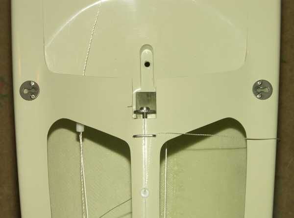 Directly above
the mast step. Directly above
the mast step.
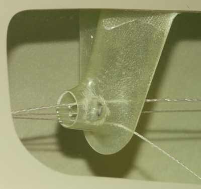
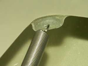
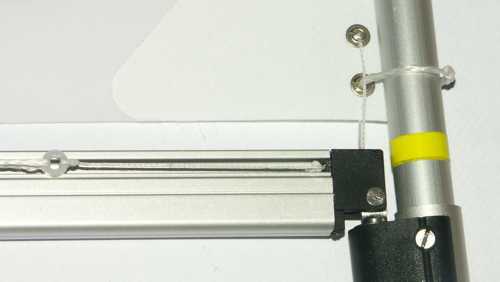
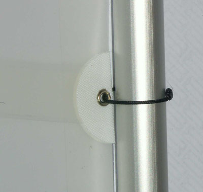
 Inside the
bows, showing the fitting of the device which holds the turning block for the
sheet control line. Inside the
bows, showing the fitting of the device which holds the turning block for the
sheet control line.
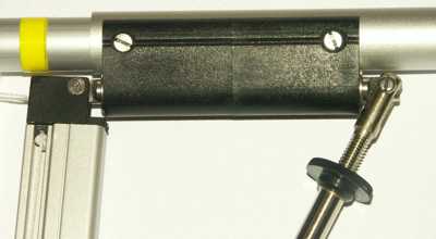
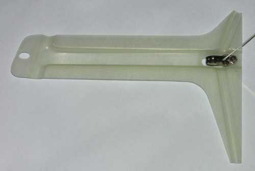 The bows
device and turning block extracted from the hull. The bows
device and turning block extracted from the hull.
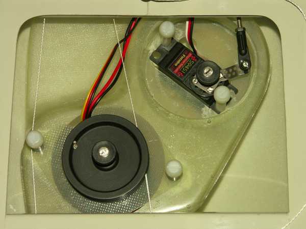 Servo tray
forward of the pot. Servo tray
forward of the pot.
 Recessed pot, aft of
the servo tray. Recessed pot, aft of
the servo tray.
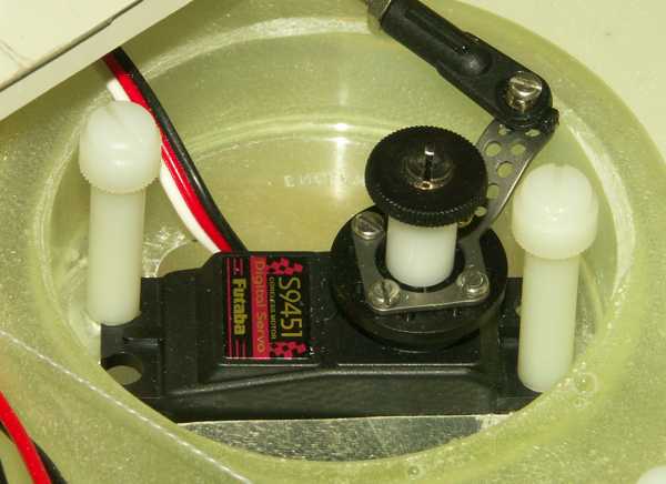 Detail of the
rudder servo installation with quick release fittings (part 67c). Detail of the
rudder servo installation with quick release fittings (part 67c).
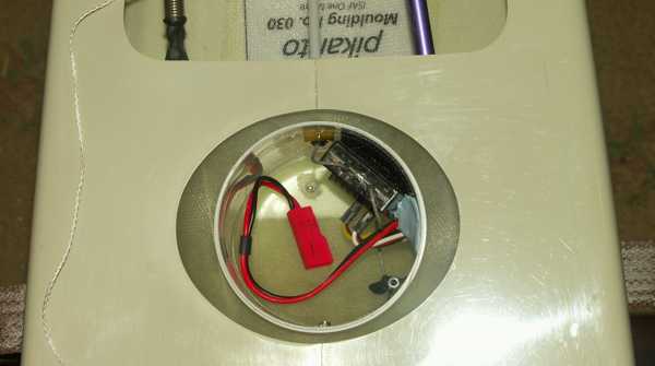
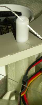
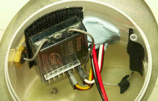 Detail of the receiver
installation. Note the routing of the one aerial wire into an open tube
stuck to the side of the pot. Detail of the receiver
installation. Note the routing of the one aerial wire into an open tube
stuck to the side of the pot.
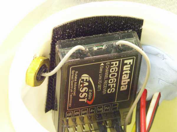 Detail of the receiver
installation. Note the routing of the second aerial wire into the tube in
the side of the pot. Detail of the receiver
installation. Note the routing of the second aerial wire into the tube in
the side of the pot.
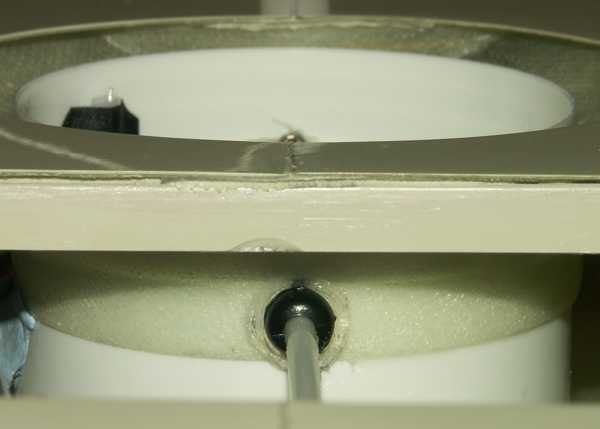 The tube in the side
of the pot carrying the aerial wire. The tubes are available from Ken
Binks. The tube in the side
of the pot carrying the aerial wire. The tubes are available from Ken
Binks.
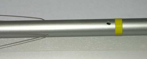
 The aft deck.
Aerial tube, spring tensioner for the control line, and arrow shaft for the
rudder linkage. The aft deck.
Aerial tube, spring tensioner for the control line, and arrow shaft for the
rudder linkage.
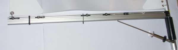
 Main sheeting post
between pot and servo tray. Main sheeting post
between pot and servo tray.
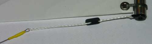
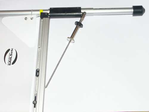
 Detail of the control
line tensioner. Detail of the control
line tensioner.
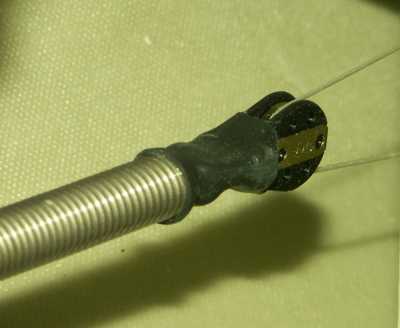 Detail of the
turning block attached to the control line tension spring. Detail of the
turning block attached to the control line tension spring.
 Aft deck. Aft deck.
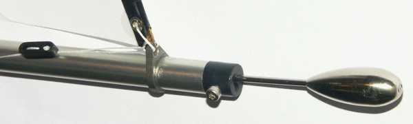
 Detail of the rudder
stock linkage. Detail of the rudder
stock linkage.
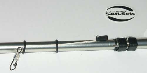
 The aft under
hull looking down the rudder, showing the calibration marks for 55 degrees of
throw either side of centre. The aft under
hull looking down the rudder, showing the calibration marks for 55 degrees of
throw either side of centre.
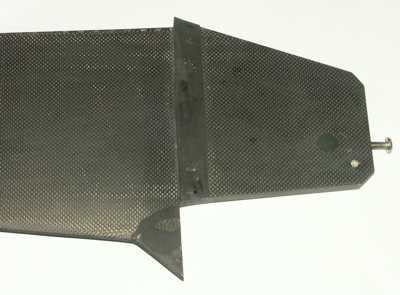
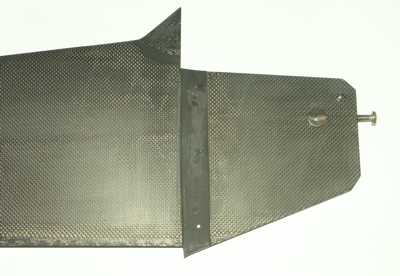 Fin tongue. You
can just see the M2 set screws for fin alignment. Fin tongue. You
can just see the M2 set screws for fin alignment.
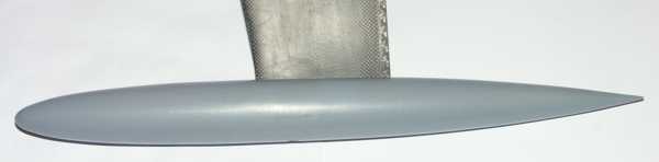 The bulb. The bulb.
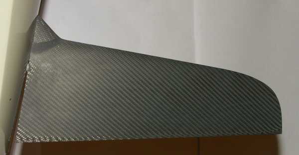 Rudder. Rudder.
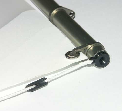
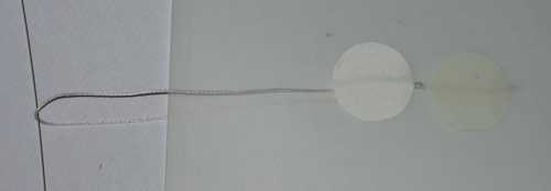
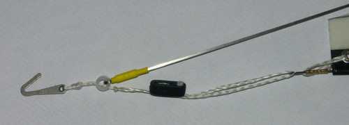 Detail of
jibstay attachment with topping lift attached to small acetal ring (part 85) threaded onto
the jibstay. Detail of
jibstay attachment with topping lift attached to small acetal ring (part 85) threaded onto
the jibstay.
 Detail of fore end
of jib boom. Detail of fore end
of jib boom.
 Detail of jib
boom pivot pin and sheet attachment. Detail of jib
boom pivot pin and sheet attachment.
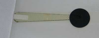
 Detail of aft
end of jib boom, showing topping lift and clew. Detail of aft
end of jib boom, showing topping lift and clew.
 Topping lift
restraint line attached to jib leech. Topping lift
restraint line attached to jib leech.
 Batten at jib leech. Batten at jib leech.
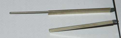
 Lower end of mast. Lower end of mast.
 Main boom. Main boom.
 Gooseneck
pivot and downhaul. Gooseneck
pivot and downhaul.
 Gooseneck fitting
(part 11c). Gooseneck fitting
(part 11c).
 Main boom
and downhaul / Cunningham bowsie. Main boom
and downhaul / Cunningham bowsie.
 Main boom
aft fittings. Main boom
aft fittings.
 Main boom
sheet reeving fitting. Main boom
sheet reeving fitting.
 Luff tie. Luff tie.
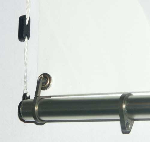
 Hounds and jibstay
attachment hole. Hounds and jibstay
attachment hole.
 Spreaders. Spreaders.
 Shroud
attachment fitting (part 31s). Shroud
attachment fitting (part 31s).
 Mast crane. Mast crane.
 Lower end
of backstay. Lower end
of backstay.
|