![]()
![]()
![]()
![]()
![]()
![]()
|
|
|
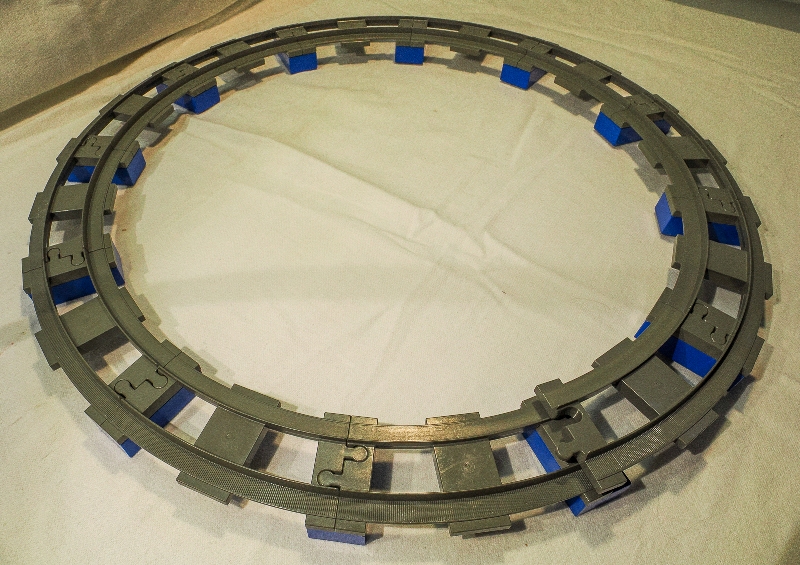
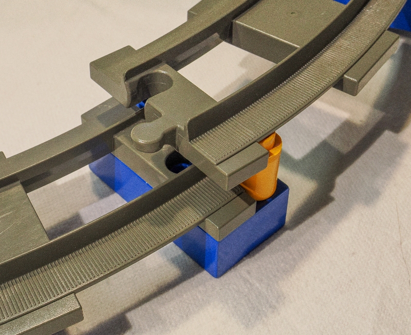
I played with Lego train sets for many years, but found my collection periodically outdated -- that is, additional track and spare parts no longer available -- as Lego moved from 4.5V to 12V to 9V and back to 4.5V over the years. I changed my allegiance to Duplo trains, much easier to set up for a quick play, less churn on the basic design, and much sturdier when young kids visit. I started making simple layout designs by sketching them in Corel Draw, and soon discovered that a promising circuit either wouldn't "join up" on the screen but was fine on the floor, or joined up perfectly on screen but failed to do that on the floor. Being Duplo, the designed track clearances meant we could go ahead anyway and have fun in a way that simply wasn't possible with Lego track. I began to wonder why theory and practice did not correspond. Curved trackIt turns out that there are four varieties of the Duplo track curve with subtle differences. The first "black" track used 8 curves to make a circle, and for convenience this can be called Generation 0. The system was redesigned in around 1993 to use 12 curves for a circle, and the first products of Generation 1 were in dark grey. A little while later Generation 2 appeared in a dark bluish grey, while the current Generation 3 appeared in light grey. (I've not been able to find reliable dates for the changes. Some sources agree that Gen 2 appeared in 2005, and some suggest that Gen 3 was brought into production from 2018.) It turns out that only Gen 3 light grey curves actually make an exact circle, while curves of Gen 1 and/or Gen 2 don't meet up properly. The pictures below show how much a Gen 1 circle is tighter than expected (Gen 2 is the same). The orange spacer in the second picture helps show the amount of overlap. In all of these pictures, the tracks are locked in place by bricks, eliminating the designed tolerances to better see the exact geometry of the track elements.
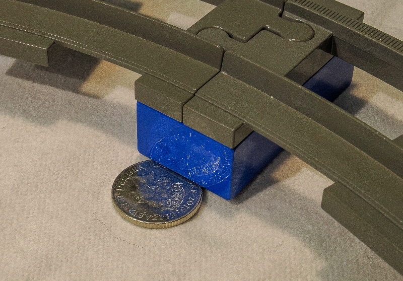
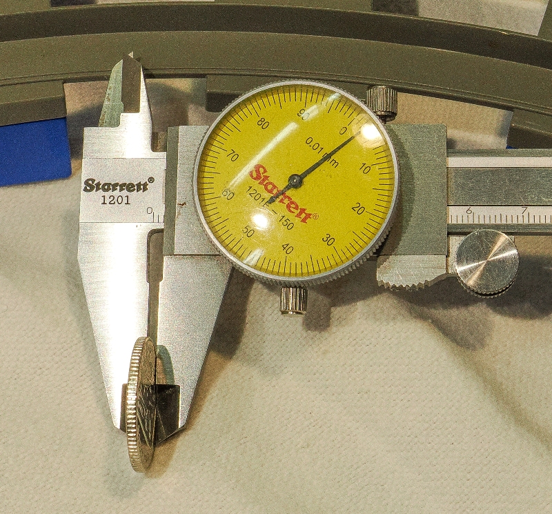
A second curious aspect of the Gen 1 and Gen 2 curves is how they do not lie flat when joined up. The inside of the circle lifts up by around 2 mm, as shown in the next two pictures, the thickness of a 10p coin.
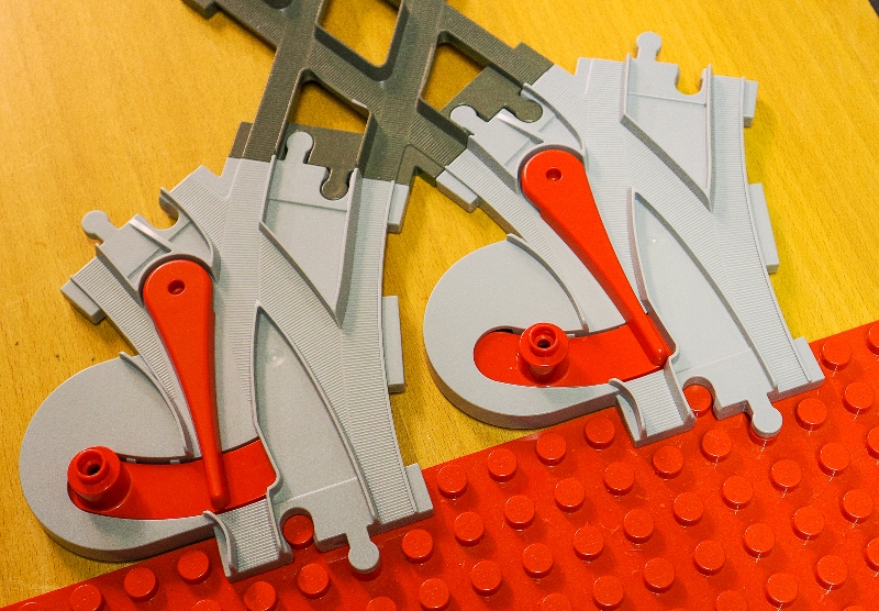
The Gen 3 curves have fixed these issues. They lie flat and join up perfectly. Of course, due to the designed tolerances, Gen 1 and Gen 2 tracks meet up perfectly well in practice with a little pushing and shoving on the floor. Similar observations have been made by Robert Cailliau. (You may like to Google Robert, he is "Google Prime".) Points or SwitchersThere are four varieties of Duplo switchers as they are called by Lego, again with subtle differences. The first "black" Gen 0 switchers were not points or switchers, just "Y" joiners, while a system redesign gave Gen 1 spring-loaded switchers in dark grey (disassembled for interest by Robert). Gen 2 switchers were a complete redesign, much simpler without any spring, and the current Gen 3 are unchanged from Gen 2. At first glance, the switchers of Gen 1, 2, and 3 seem to comprise a pair of opposite-orientation curves, and that is how they fit quite happily into track layouts, replacing a single curve with a switcher. What is very interesting is that their geometry isn't the same as the single curve. Instead, the switcher seems to have been designed to work with the Gen 1 or Gen 2 "X" type cross-over (with straight sections at 60 degrees, where Gen 0 used a "+" type cross-over with straight sections at 90 degrees), such that the switcher curve geometry has been adjusted as shown below. (Note the "X" cross-over is out of production since around 2016, it has not been seen in the light grey Gen 3 colours and is not part of any current Duplo train set.) The following picture shows an "X" cross-over connected to two Gen 3 curves. Note that, when one curve is fitted the baseboard, the second curve does not fit, it is offset by about a half-stud. Not usually a problem with a layout on the floor, but on the computer screen little gaps can materialise between subsequent layout elements.
When an "X" cross-over is set with two Gen 3 switchers, though, they both fit to the baseboard with an exact 4-stud gap between them. As far as I know, this also happens with Gen 1 and Gen 2 switchers, they have the same geometry.
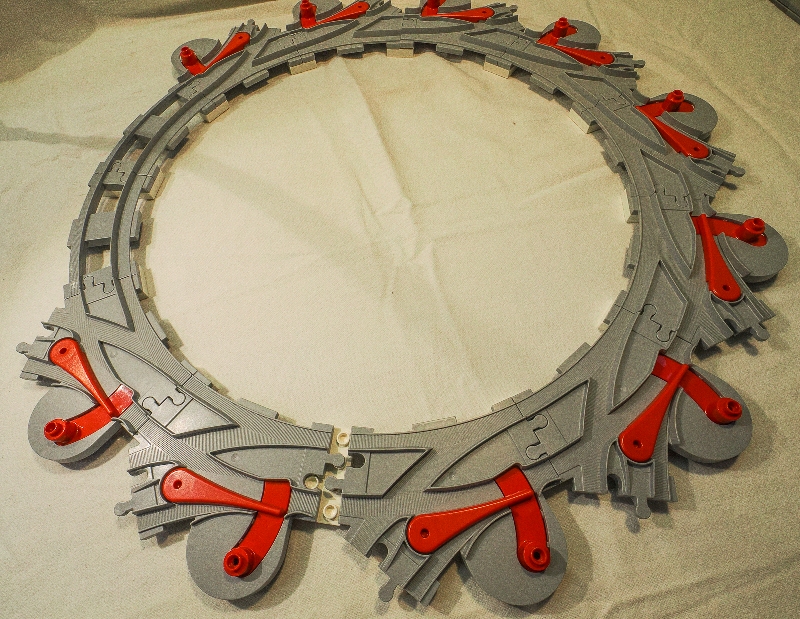
It turns out this is a very desirable property of two switchers connected to an "X" cross-over when designing "computational" layouts. For interest, when the Gen 1, 2, and 3 switchers are connected into a circle, they do not meet up, being too far apart by around one stud, as shown by the next picture. This is opposite to the way the Gen 1 and Gen 2 curves do not meet up, where in those cases their circle is too tight. (Only 10 Gen 3 switchers in the pictured circle, with 2 Gen 3 "perfect" curves. Sorry, not enough switchers in my collection!) Again, on the computer screen, gaps can materialise between subsequent layout elements when switchers are introduced.
|
|
©2025 Lester Gilbert |