![]()
![]()
![]()
![]()
![]()
![]()
|
|
|
(Minor edits September 2023) This page provides the instructions for and examples of use of the various laminated label tapes available for purchase from SAILSetc. The "Hull pack" contains the rake and sheeting gauges, while the "Rig pack" contains the draft and twist gauges and the boom hole spacing template. Rake gauge
GeneralThe gauges are printed onto Brother TZ thermal 24 mm wide laminated tape. Production is currently "black on clear" for hull gauges, and "black on white" for rig gauges. (The examples shown here are printed black on white or red on clear. These are all "pre-production" sample illustrations.) For "black on clear" gauges, the background of whatever the tape is attached to will show through, and makes the result particularly attractive when set to a coloured deck, for example. There is a problem if the background is a dark colour, as would happen with a hull finished in natural carbon fibre, so the hull gauges are now available "white on clear" as a special order. All the gauges (with the exception of the rake and draft gauges) are designed for "right-handed" use. This does not mean that they are used or attached to the starboard side of the boat, or even that they are normally held in the right hand! A right-handed sailor would usually place their boat port-side down, and then work on the starboard side of the boat from behind using their right hand. In this case, the sheeting and twist gauges are actually held in the left hand and are positioned or used on the port side of the boat.
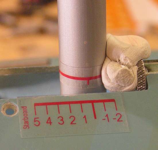
Rake gauge
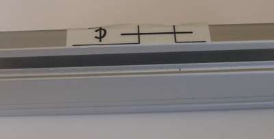
The tape comes with four "mast indicators" at
The gauge markings have a 2.6 mm pitch. These give rake readings in degrees, if you have a depth of 150 mm from where the gauge is set to the bottom of the mast step. If your hull has some other distance between the gauge and the mast step, well, the numbers will just provide arbitrary units rather than a reading in degrees.
The picture shows a length of mast tube set at 0 degrees rake for calibration and temporarily held in place by some putty, the indicator strip set on the tube, and the gauge then positioned as required on the deck.
Main & jib sheeting angle gauges(Note SAILSetc now sell their own design of simplified sheeting gauges)
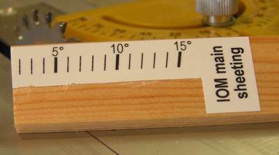
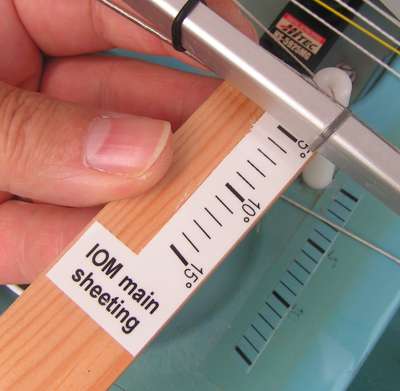
The main sheeting angle tape provides two gauges. The top gauge at
The bottom gauge at
The picture illustrates the top gauge from the main sheeting tape set onto a probe, a length of pine 25 mm wide by 4 mm thick. The bottom gauge has been trimmed away to prevent any, ah, confusion on the part of this drowsy sailor. In either case, the same gauge is used for all rigs. The gauge markings read in degrees if the main boom sheeting radius is 195 mm or thereabouts to the location of the sheeting post. If your sheeting post involves a different sheeting radius, then these markings are arbitrary units.
In the above example photo, the main sheeting gauge is reading a main boom sheeting angle of around 5 degrees.
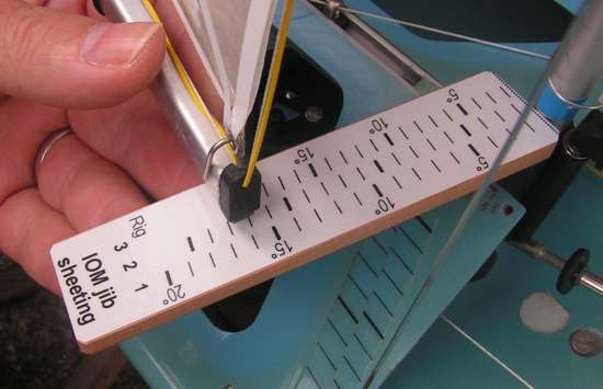
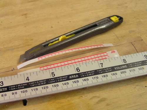
The jib sheeting angle tape is intended for use on a probe, where it is held
against the mast and the sheeting angle read off from the end of the boom.
Two trim lines at
The gauges read in degrees on the assumption that the jib boom pivot is located at 22.5% of the jib foot, giving sheeting radii of 295 mm, 270 mm, and 230 mm respectively to the end of the jib boom for each rig.
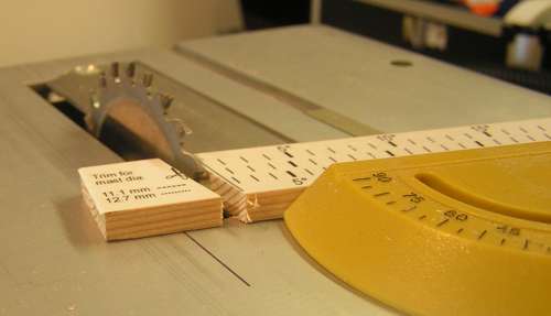
The picture above shows the probe being trimmed to suit a 11.1 mm dia mast. Although it cannot be seen in this picture, the main sheeting gauge has already been attached to the reverse of the probe, so both sheeting gauges are on the one probe.
The jib sheeting gauge is reading a jib boom sheeting angle of around 16 degrees in the above example photo, given that this is the No.1 jib. You may notice in the photo that my Italiko already has an "old" sheeting gauge stuck to the deck. If your deck is flat, then you might find it more convenient to stick your new sheeting gauge to the deck rather than to a probe. However, if your deck slopes, then the gauge will over-read due to parallax. If you are not too concerned about reading the numbers as degrees, then this is not a problem. You can treat the numbers as arbitrary indicators, which happen to keep their relationship between the rigs. This means, for example, that if your jib boom reads "12" on a gauge stuck to a sloping foredeck in No.1 rig, and also reads a "12" in No.2 rig, then you have the same sheeting angle for each (whatever that angle might be!). However, if you would like a gauge corrected for to a 30 degree deck slope (as on any recent SAILSetc IOM), then this is available as a special order. The "special" also rakes back 15 degrees to follow the foredeck aft edge, as in the "old" gauge shown in the above photo, keeping free of the area where a deck patch would be attached, and thus allowing a more permanent fixing. (If you don't want the "special" but do want to know how much the "normal" gauge would over-read on a 30 degree sloping deck, the answer is around 15%, or approximately 1/7. So a reading of "14" on a gauge sloping at an angle of 30 degrees would indicate an actual sheeting angle of around 12 degrees.)
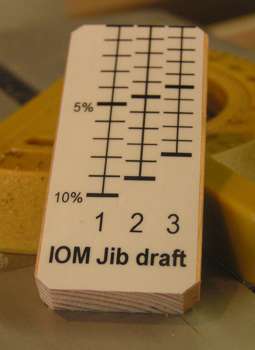
Main & jib draft gauges
The draft gauges are intended to be set on a probe, and are trimmed at
either
The draft indicator is attached to the top of the boom, such that the
reference line, arrowed, aligns with the edge of the boom track. The boom
centre-line is then correctly located, offset 2.5 mm from the edge of the boom
track. The "alternative trim line" provided at
The draft reading is a percentage of foot (chord) length, and is calibrated to the foot lengths of the IOM main and jib for each rig. The two gauges can be attached to a single probe, one per side.
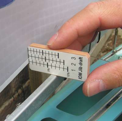
The picture shows the probe for jib draft, trimmed at
The jib draft gauge is reading a jib draft of around 6% in the above example photo (No.1 jib). (Note that in this picture the draft indicator has not (yet!) been attached to the boom.) The pitch of the measurement lines on the draft gauges are calibrated to the way the gauges are used. By pressing (very gently!) against the foot of the sail, the gauge makes the sail foot take up a triangular shape, rather than a free-flying aerofoil shape. This would normally cause the gauge to over-estimate the sail draft, as illustrated in the diagrams below. The value of h' (height of triangle) is larger than the value of h (height of aerofoil). Using a spreadsheet (Gauges/Draft.xls, 21 kb), however, the over-estimate can be approximately calculated and corrected. The gauges provided here incorporate the correction, and read "true" draft when the sail foot forms a shallow triangle during measurement.
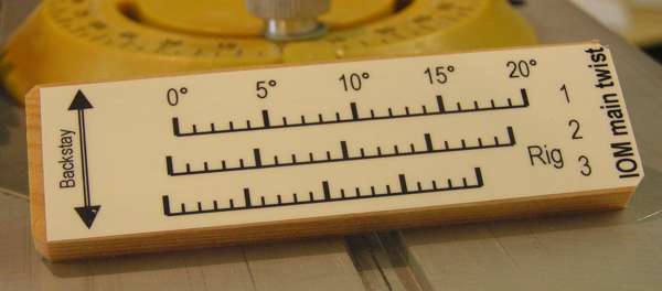
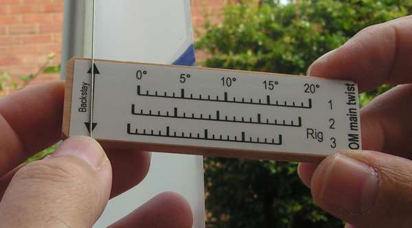
Main & jib twist gauges
These two gauges are intended to be attached to a measuring stick, and do not need trimming at any particular point. For both gauges, the twist is measured from the aft end of the top or upper batten for IOM rigs. The main twist gauge is used by being set against the backstay at
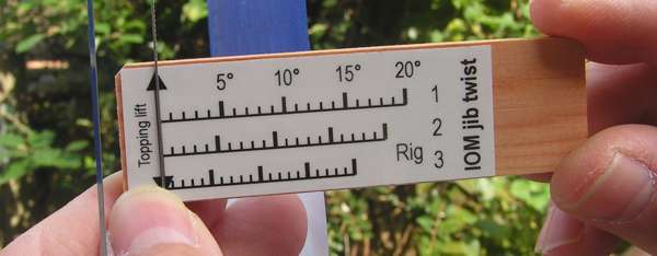
Similarly, the jib twist gauge is set against the topping lift at
The picture shows the gauge mounted to a measuring stick. (Note that the picture shows a LH gauge.)
The jib twist gauge is reading a jib twist angle of around 12 or 13 degrees in the above example photo, measured at the upper batten for the No.1 jib.
The main twist gauge is reading a main twist angle of around 6 or 7 degrees in the above example photo, measured at the top batten for the No.1 mainsail. The theory of the twist gauges is shown on the pages to do with Twist measurement and Twist measurement (part 2).
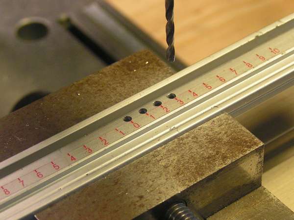
Boom hole spacing template
Three gauges are provided at
The hole spacing represents a one-degree change in sheeting. For the jib booms, this assumes a sheeting radius (distance between jib pivot and sheet attachment point) of 210 mm for each rig, and a resulting hole pitch of 3.67 mm. The hole spacing for the main booms assumes a sheeting radius of 195 mm, and a resulting hole pitch of 3.4 mm.
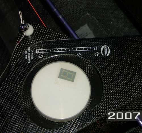
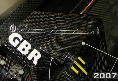
While a sharp drill bit will easily drill through the tape material, it will still leave a rough edge when withdrawn. The picture shows the tape trimmed sufficiently so that the holes can be drilled above it, allowing a clean result. Hull gauges for SAILSetc SWORD 'A' ClassThese are a set of 'specials' in white lettering on a transparent background (so they show well on the carbon fibre of the hull) and the SAILSetc logo. The following two pictures illustrate their positioning. (They are not suitable for other 'A' boats, because they are angled quite sharply to follow the deck patch orientation of the SWORD design.)
Part of the main sheeting gauge has been trimmed away where it overlapped with the recess for the pot.
Both gauges are positioned forward of the deck sheet fairleads, at the distance
indicated on the gauge from the boom pivot point (260 mm for the main gauge from
the 0 degrees position, 340 mm for the jib similarly), and are set at an angle,
parallel to the edge of the nearest deck opening. |
|
©2025 Lester Gilbert |