![]()
![]()
![]()
![]()
![]()
![]()
|
|
|
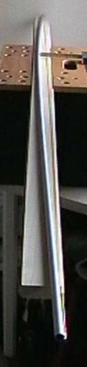
Pre-bend the mastThe minimum permitted mast diameter for the IOM is 10.9mm; for a keel-stepped mast, we are looking at a mast length of around 1800mm, and that makes for something not far short of soggy spaghetti. To get the sort of stiffness out of such a thin piece of aluminium alloy (carbon fibre is not permitted) needed at the very top of No.1 suit wind range, we need good rig tension. And the only way to get that is to pre-bend the mast -- that is, to bend the mast opposite to its normally rigged bend. Without pre-bend, the SailsEtc 11.1mm diameter 0.7mm wall thickness circular section tube allows a backstay tension of at most 1.5lbs, after which the main sail head just looses all its shape. With pre-bend, you can run around 3.5lbs backstay, and the jib will now behave itself in all winds. It is not a free lunch, of course; with very light airs the jibstay will not sag at all and your jib shape will have to come exclusively from the outhaul setting. By the way, if you are going to run with mast pre-bend, you'll need a sail box; a sail bag won't do. You'll also need to adjust how you store the rig in your sail box accordingly. In a nutshell, you'll have to clamp the mast in the box into its normally-rigged bend so that the sails aren't stretched out of shape.
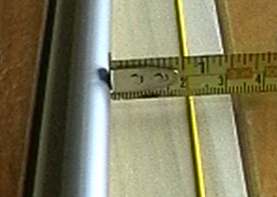
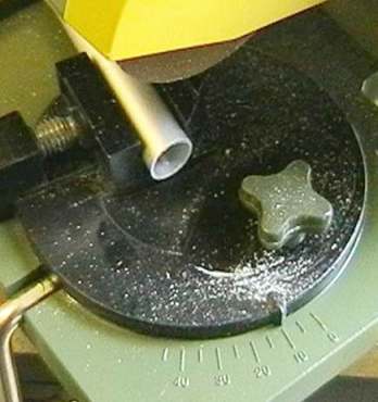
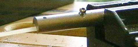
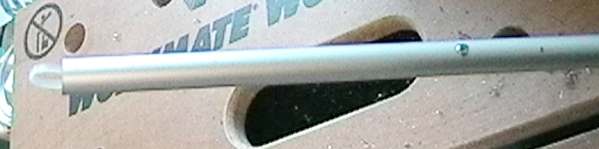
I begin with a 2000mm length of 11.1mm circular section alloy tube from SailsEtc, and pre-bend it according to their instructions. Well, this particular one was bent by Graham Bantock. Most of the bend is placed in the upper 2/3rds of the mast. If measured mid-mast, as shown, then we want about 20mm. A length of elastic from head to foot gives a straight-edge for comparison. I'll probably increase this to 30mm to get the sort of jibstay tension I'm after, since I sail with a jib with negligible luff allowance. Graham Bantock checks the pre-bend by holding the head of the mast in one hand, placing thumb and finger of the other hand at the jibstay position, and bending the mast the way it would bend as though held by backstay and jibstay. The mast should then set into a nice, fair curve to match the mainsail luff curve. There is an argument about whether to pre-bend the mast first and then add the fittings, or put the fittings onto a straight mast, and then pre-bend it. Answer below... Trim to lengthThe bottom 20mm of the mast is trimmed off. The trim angle is 80 degrees, not 90 degrees. This is shown in the photo, where the clamp has been set at 10 degrees off square. This chamfer of the mast step puts the longer face of the mast forward, so when the shrouds are tensioned they help the mast take up its required rigged bend. The chamfer also allows the mast heel fitting to sit more comfortably in the fin box as the mast bends.
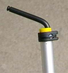
The bulk of the trim takes place at the head of the mast. It is difficult to pre-bend the very top of the mast, so it makes sense to cut away most of the excess here, leaving the pre-bend curve running right up to the head. And that's why I pre-bend the mast before adding the fittings... I make the trimmed mast length up to 1790mm. This allows for 25mm between the top of the gooseneck body and the lower measurement band, and 10mm at the head of the mast between the top measurement band and the head fitting. Fit the gooseneckI vary the gooseneck tilt (as per the gooseneck page) depending upon wind speed. I need to put a reinforcing piece inside the mast so I can screw and unscrew the gooseneck as required, to slide a shim under the lower body. This needs a bit of work to get the reinforcing piece just where I want it.
First, I cut a length of 11.1mm SailsEtc "joiner" section, and screw a cable tie to it so I can move it around inside the mast. Then I drill and counter-bore the centre of the reinforcement and screw in a small self-tapping pan head screw. The photo shows the screw not yet fully seated.
The reason for the screw on the reinforcement piece is shown in the photo above. With the reinforcement piece slipped inside the mast (the cable tie is tucked back inside at the foot), the screw head fits snugly into a suitable hole drilled in the mast, so that the reinforcement piece doesn't wiggle about as the rest of the holes are drilled to take the gooseneck body. If the reinforcement piece isn't held in place, there is no way you'll get a set of clean holes for the gooseneck body. To find the correct gooseneck placement on the mast, be sure to check that the kicking strap can move freely even when the mast is raked right back. The SailsEtc ball-raced gooseneck has to be set about 15mm above deck level, while the "normal" gooseneck can be set at 10mm. If you want to settle the rig lower, you can gain about 10mm by setting the gooseneck lower, but you'll have to take particular measures to prevent the kicking strap from scraping along the dished deck of the Ikon. First, you'll need to shorten the standard kicker and attach it somewhere around 100mm from the gooseneck rather than 180mm. Then, you'll need to replace the lockwheel with a nut. Also, you'll need to make sure that the operating range of the kicker adjustment screw is no more than 5 or 6 turns screwed in, otherwise the knurled knob of the adjuster will foul the deck. Finally, you will need to attack the point where the foredeck arrests the main boom with a file, because it does this on the kicking strap. A shortened kicking strap will only allow the main to sheet out (on a standard Ikon) to about 80 degrees at best, and 70 or 65 degrees at worst (when the mast is raked forward). Don't try this on an Image; there is nothing to file away.... The above surgery might be considered worthwhile with the ball-raced gooseneck, since it carries the main boom about 5mm higher than the standard gooseneck. If you try this with the standard gooseneck, however, the boom fouls the mast partners, and pretty much defeats the point of the exercise.
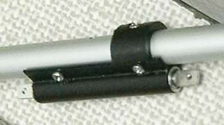
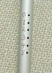
To finish the gooseneck area of the mast, the "deck fitting" is trimmed to size and screwed to the mast. The deck fitting in this case is a cut-down heel fitting, and is positioned to chock the mast at the partners. The deck fitting must be screwed, and not simply taped to the mast, since it needs to be a gentle, but definite, force-fit into the partners. We don't want the mast rattling around there. After a number of riggings and de-riggings, the deck fitting can spring out of the partners if it is not screwed in place. The ball-raced gooseneck comes with a 1.8mm drill bit for the screw holes. This is the right size for moderate reinforcement in the mast, but for the joiner section I use, it is a little too small. The self-tapping screws will break, so 1.95mm (5/64ths) or 2mm holes are better. Drill rigging holesAfter placing the spreader and shroud holes, I drill a set of holes for the jibstay. Instead of varying jibstay length with a bowsie, I use a fixed length jibstay, and hook it into one or other of the holes on the mast. The holes are spaced at 6mm; this means that each hole changes mast rake by 1 degree. I set the jibstay on the mast with a hook length which, when inserted in the "0" degrees rake hole, does indeed give me 0 degrees rake. From there I know exactly which hole to use for which wind speed range. The top-most "0" degrees rake hole is 10mm below the middle measurement band.
Fit backstay craneThe second-to-last task is to complete the mast head. The mast head fitting and the backstay crane must be screwed to the mast. The reason for this is that, particularly with pre-bend, backstay tension can work the crane and the head fitting around in the mast. This takes the head fitting off centre, rotates the mast, un-centre the gooseneck, and generally causes unpleasantness, back ache, and depression. Since I'm putting a screw in, I add a 10mm boom band, slit at the rear, so I have a hole into which I can drop a wind vane for light or shifty airs. The boom band is shaped so that a rubber "O" ring holds the wind vane in place. Yup, these are all SailsEtc fittings. The boom band forms the top measurement band; in theory, the mast is not permitted to have anything which varies its cross-section between the bottom and top measurement bands (apart from a joiner section if the mast is in two parts). The boom band attachment for the wind vane, while certainly a permitted fitting, is probably not permitted below the top measurement band, so it is convenient to have it form that measurement band instead.
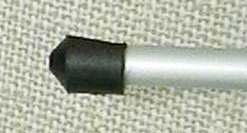
Add mast heelThe SailsEtc mast heel fitting must be trimmed on its forward face, so that the mast can be stepped completely vertical. If the heel fitting is not trimmed in this way, the mast will have a minimum rake of around 1.5 degrees instead of 0 degrees with the standard fin box. If you then need to rake the mast further forward (right at the top of "A" rig wind range, for example) the mast will take up a very awkward bend just around the gooseneck and the sail will not set properly at all. The heel should be fixed to the mast with a small self-tapping screw. I was beside myself with frustration at one race when, on de-rigging the "A" suit to change down to "B" in a hurry, the heel got left behind in the fin box, and there was no way it was going to make an appearance in time for me to start that race...
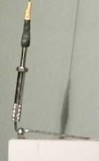
The gooseneck reinforcement, and the backstay crane, are made of hard alloy, and need care while drilling. I put a drop of oil or paraffin on the drill bit, and that makes life a lot easier. Also, I keep the drill speed right up with the small diameter bits involved. All the screws I've mentioned are the little #2 3/8" self-tappers as supplied with the gooseneck kits, and available separately if required. If you are starting off for the first time, the SailsEtc rigging plan (catalogue number 16d) is a must. Other detailsOne picture shows the shape of the rigging screw wire used for the shroud attachment to the deck eyelet. It gives fast rigging and de-rigging. In practice, I've changed down from No.1 rig to No.2 rig in 90 seconds, so I can make my final decision at the 3 minute warning.
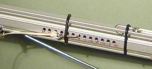
The other picture shows the adjustment holes on the main boom for the sheet attachment. These holes are spaced at 3.5mm, which means that each hole represents a change of one degree of sheeting. If I want the main to be fully in at 5 degrees instead of 3 degrees, for example, I know that moving the sheet hook two holes does the trick. 2018-06-23 |
|
©2025 Lester Gilbert |