![]()
![]()
![]()
![]()
![]()
![]()
|
|
|
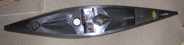
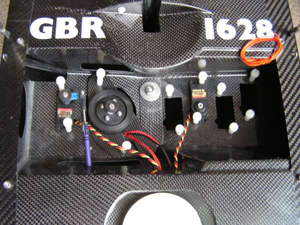
The weight budget is interesting:
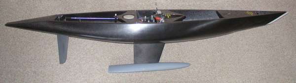
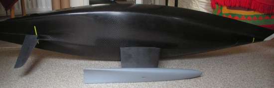
... yielding an amazing 81% ballast ratio. I asked for a servo tray to take a winch and five servos. In due course, I hope to have additional channels control a trim tab on the fin, give independent trimming of the main sheet, and adjust main and jib draft and twist. The fin is secured with the large washer and nut. There are four socket-head screws at each corner of the tray opening. While these are removed for normal sailing, they make provision for mounting a plate to take the heel fitting for a towing post for use in a towing tank. I'm planning ahead to use the hull in the University of Southampton's Lamont towing tank to explore fin and bulb configurations.
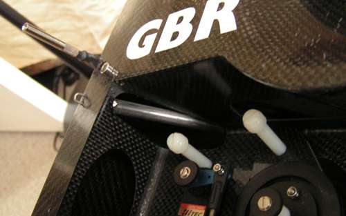
The chainplate on each side has a pair of c/f reinforcement rods, one from each of the shroud attachment points, running to the fin box. The photo shows one of these.
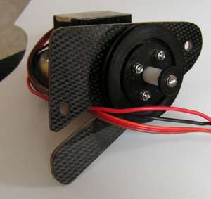
The RMG winch is mounted on a plate via the SAILSetc quick-release fittings, and carries a drum I've turned of around 45 mm diameter.
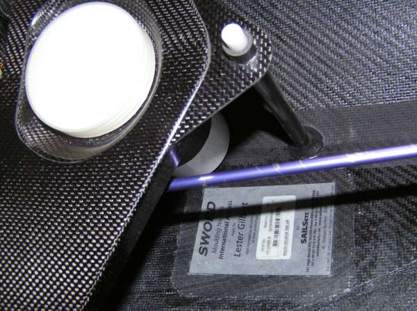
The main sheet post is an Acetal rod carried in a c/f tube which is bonded at both deck and keelson. A small screw fixes its height. The plaque identifies the hull as moulding 009.
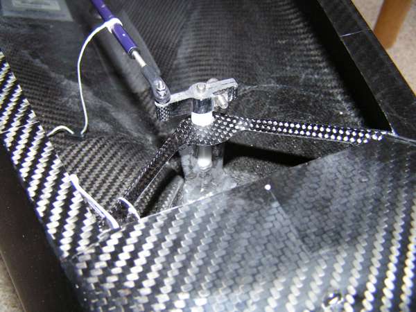
The PTFE rudder trunk is located by a c/f moulding.
The rudder is a high aspect ratio item, with draft just a few centimetres short of overall boat draft.
The foredeck photo shows the jib pivot arrangement. The foremost pivot is the now-established SAILSetc Dyneema swivel and ring for No.1 rig, and recessed wire loops for lower rigs. For my boat, I have the area between the pivot fittings and the measurement bands specially strengthened, with the intention of mounting a custom radial arm jib fitting just as soon as I have machined one. Ahead of the measurement bands you can faintly see the turning block for the control line and the sheets, in fact a block sized for a small dinghy.
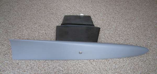
The fin has a tongue which fits into the moulded fin box. The bulb is pinned to the fin on either side of the single securing bolt.
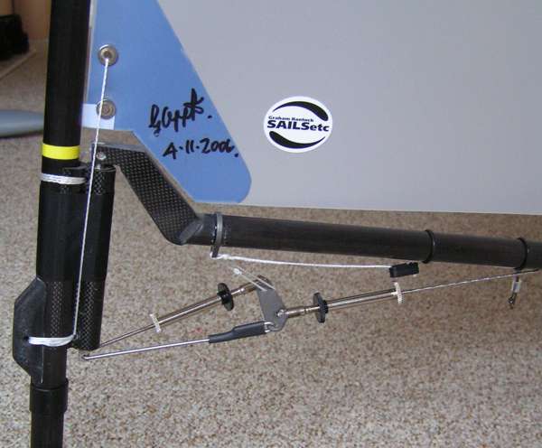
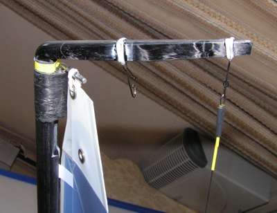
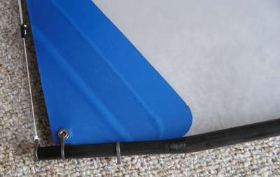
The gooseneck and kicking strap arrangement is illustrated here. The kicker is a "dual speed" arrangement, one adjuster giving coarse adjustment, and one giving fine adjustment of main twist.
The mast head carries a backstay crane with two attachment points, the aft one for No.1 rig, and the forward one for lower rigs.
Graham's lower rig main sails have interesting head extensions. These act as splitter plates aft of the mast, reducing the turbulence that an otherwise bare mast generates.
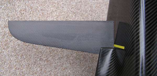
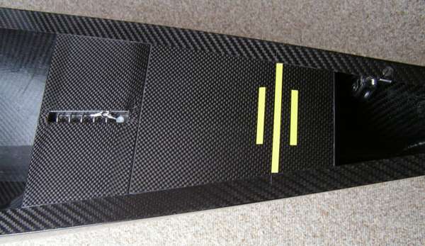
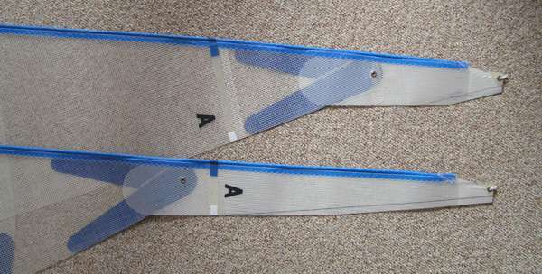
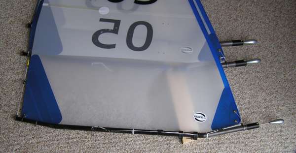
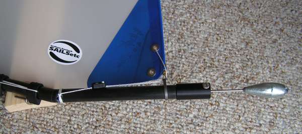
The following pictures show detail of the jib booms.
|
|
©2025 Lester Gilbert |