
![]()
![]()
![]()
![]()
![]()
![]()
![]()
|
|
|
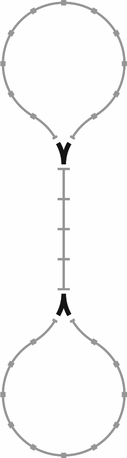
An interesting challenge when playing with track layouts is to design a circuit where the train travels around all of the laid out track with minimal or no intervention, all points visited, ideally in both directions. It is a surprisingly difficult problem, and I know of no solution apart from the simple hour glass, as below. Note that this works provided the switchers are not sprung like the Duplo Gen 1 switcher; that is, the switch can be moved to a different position by the passage of the train as in the Gen 2 and Gen 3 switchers.
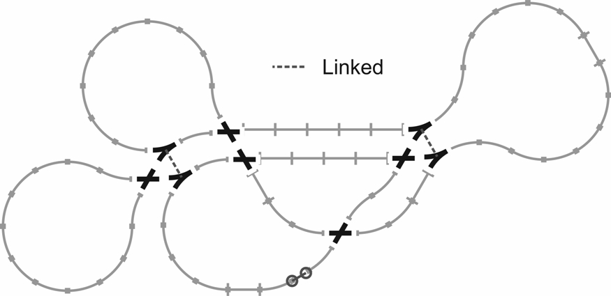
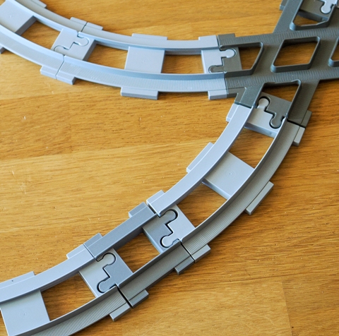
To have anything more complex, say with at least four switchers rather than two, the switchers have to be linked as explained by Guy Walker on his web page. He shows a circuit with three regions which are visited in turn, as below. This only works if, when the train changes the position of one switcher, the position of its linked switcher also changes. (The odd piece of track with small circle terminators represents a half-length straight, as pictured at the end of this page.)
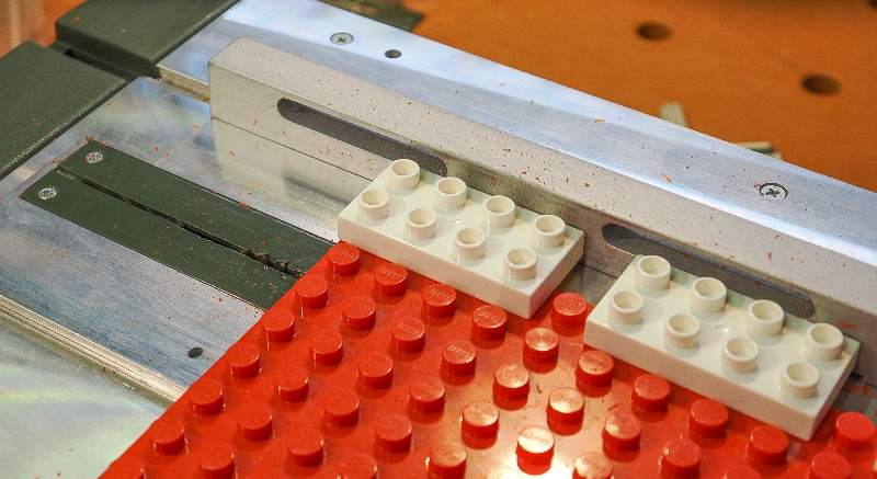
Linked switchersGuy shows a pair of switchers linked by a length of coat hanger wire looped high over the track. I tried that and found it, ah, unreliable, so decided to build a better mousetrap. It is worth noting that the two linked switchers need to be side by side in order to be linked, and the way to have them in the correct position is to connect them to a Gen 1 X cross-over. As noted in the page on Duplo track, it is only a Gen 1 X cross-over which has the property of holding two switchers side by side with the desirably exact 4 stud spacing. Hence, linked switchers can be built in a system "module" comprising a Gen 1 "X" cross-over and two Gen 2 or Gen 3 switchers, done as follows. Locking baseboard studsThe first decision was to lock the three elements of the system module (an X and two Y) with some Duplo baseboard. Cutting the baseboard into suitable lengths with my Proxxon hobby table saw needed a couple of tricks. One trick was to attach bricks to the edge of the baseboard so that it could be run against the fence and hold a constant distance from the saw, giving a strip of baseboard two studs wide. The other trick was to run the saw blade as low as possible, since the plastic is otherwise prone to shatter. The following picture shows the table saw setup.
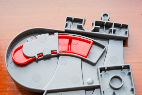
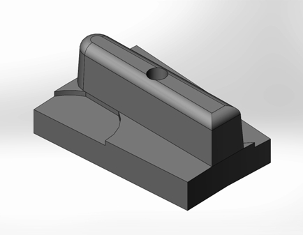
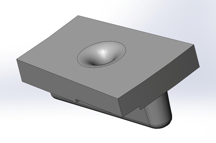
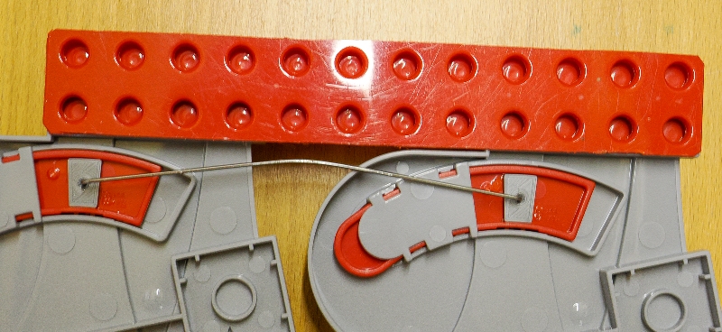
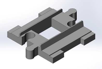
Switcher rail adapterThe linking wire needs to be attached to each switcher. There is a promising opening in the underneath of the red switched rail guide bar, so an adapter was designed, 3D printed, and glued in place, as illustrated in the next three pictures. The adapter is available as an STL file, click to download. There are two shallow crescent cut-outs on the adapter needed to clear corresponding pads on the red switched rail guide resulting from its injection moulding. The deep fillet around the hole underneath the adaptor is to accommodate the bend of the wire leg when it is inserted. In practice the wire doesn't lie flush to the adapter and so the fillet is not strictly necessary.
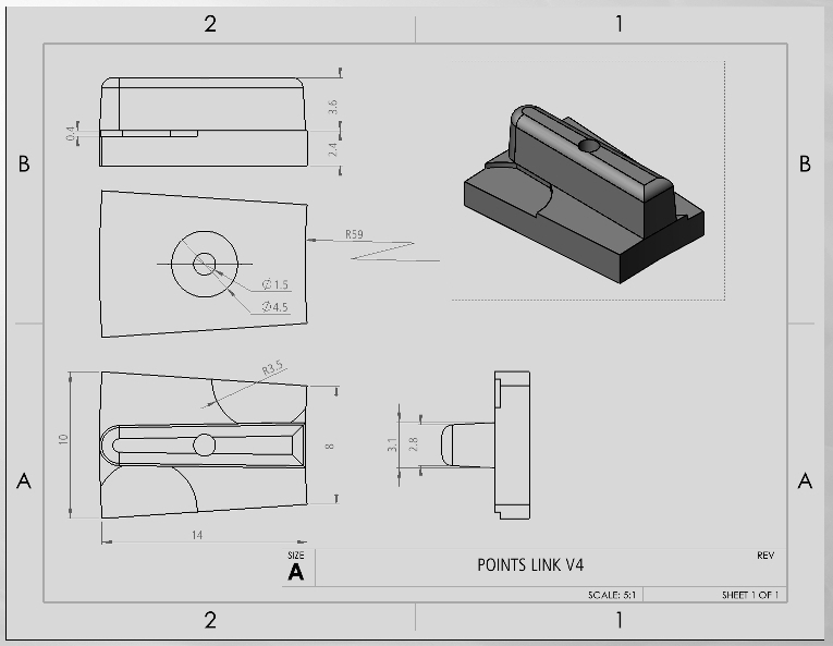
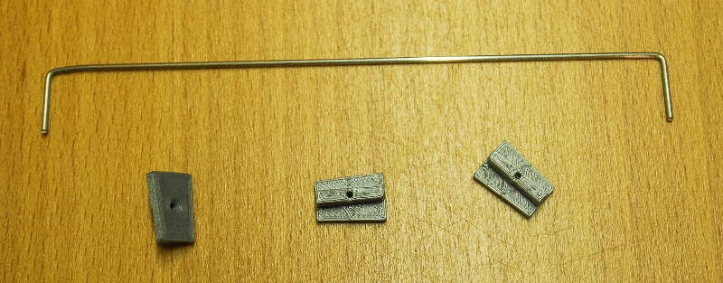
Wire linkA simple length of wire with two right-angle legs connects the two switchers. I decided to use stainless steel 1.2 mm diameter wire, this is illustrated in the following picture along with a couple of the 3D printed adaptors for scale. 1.4 mm or 1.5 mm wire would also be fine. It was more or less impossible to bend the two legs so the resulting link is exactly the right length, so the trick was to make the link slightly oversize by perhaps 2 mm, and then introduce a gentle bend in the wire to set its correct operating length, as illustrated in the later photos. The link span should be exactly 128 mm (12 studs) centre to centre, that is 126.8 mm inside and 129.2 mm outside the legs for 1.2 mm dia wire. Note that the hole for the wire leg in the adapter is sized at 1.5 mm on paper and in the STL, and prints at around 1.3 mm in practice on my Prusa. The 3D print should be cleaned with a 1.3 mm drill so that the wire leg is a freely sliding, but not a friction, fit. The wire leg should be around 9.5 mm long, where 5.5 mm sits inside the adapter with approximately 4 mm clearance when the wire runs under the switcher body.
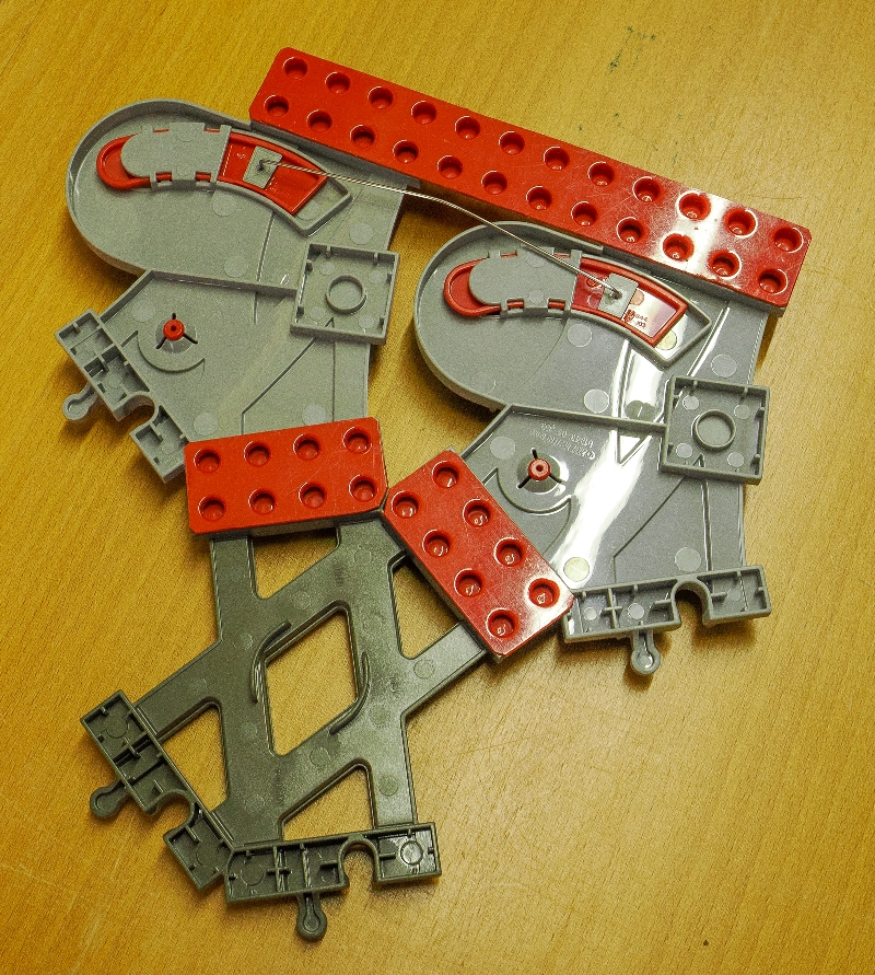
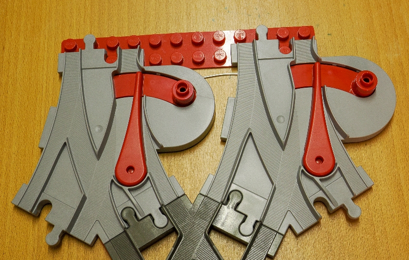
Switchers linkedThe next pictures show the linked switchers system module. Two switchers are locked to a length of 2 x 12 stud baseboard, with their adapters glued in place, the wire link inserted, and the X cross-over locked in place with a pair of 2 x 4 stud baseboards. The 1.85 mm thickness of the baseboard allows the 1.2 mm wire to run quite freely between and underneath the two switchers. The illustrations show light grey Gen 3 switchers. For unknown reasons, my Gen 2 switchers, in theory identical, showed some stiction in operation, and when used in a linked pair could cause the train to derail by failing to reset sufficiently freely.
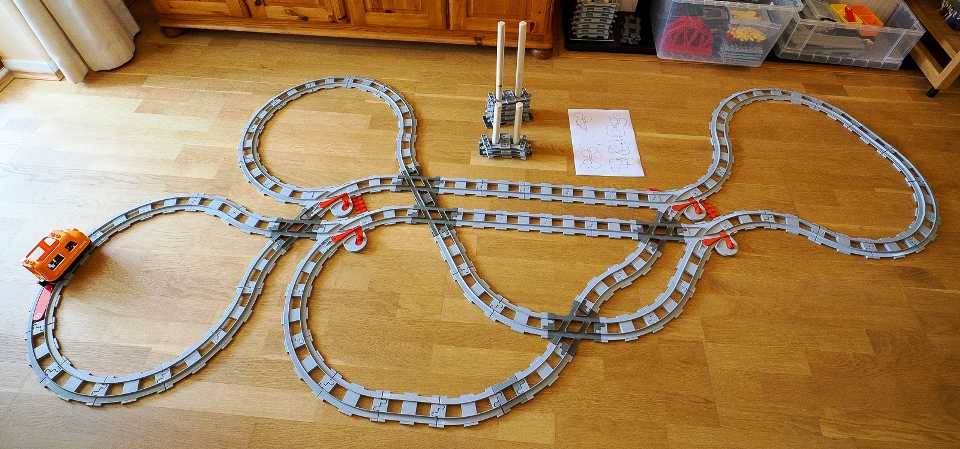
Layout with two pairs linked switchersThe resulting layout as below. (See Guy's layout here.) The picture also shows a couple of track organisers using Robert Cailliau's "rail rack" idea, next to a printout of some other versions of Guy's circuit.
The layout requires a half-length (4 stud) straight for neatness. I designed and 3D printed a version as pictured below. The STL is available here for download.
A final note is that the wire tends to drop out of the module when it is being arranged on the floor, it is a simple sliding fit after all. I cut a thin piece of transparent plastic film and placed it underneath the module with double-sided sticky tape, as in the next picture.
Added later. I thought it would be interesting to construct the CR31 layout with a bridge replacing the three "X" crossovers. Images of this version on paper, and on the carpet with some embellishments:
|
|
©2024 Lester Gilbert |
.jpg)
.jpg)