![]()
![]()
![]()
![]()
![]()
![]()
|
|
|
Design concept
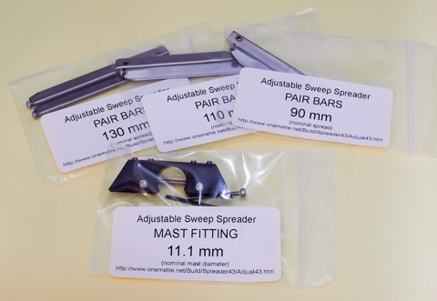
Retail packagingThe complete spreader comes as two items -- one is the mast fitting (currently to suit 11.1 mm masts), and one is the pair of spreader bars (currently three different lengths on offer).
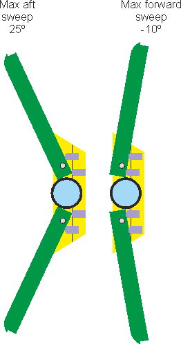
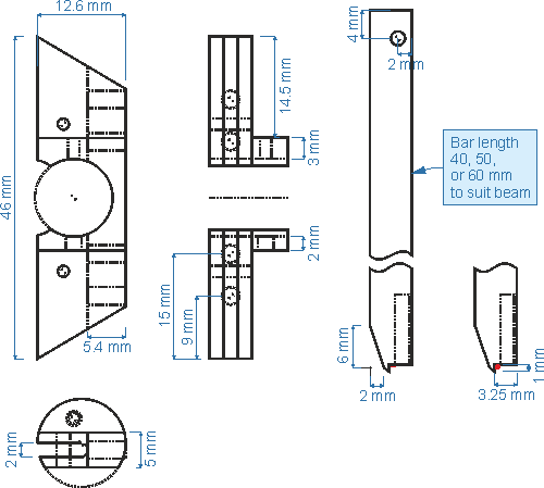
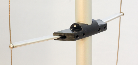
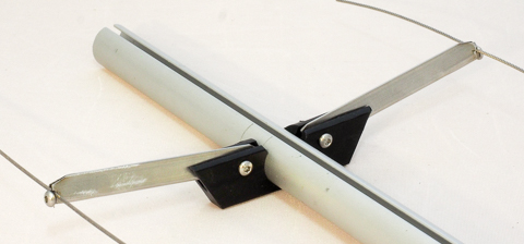
DesignThe mast fitting carries a pair of SAILSetc spreader bars (product reference SP-SB-300) whose sweep "V" is adjusted by a pair of grub screws acting on each spreader bar. Forward sweep is of up to 10 degrees (useful when high backstay tension bends the mast forward) and aft sweep is of up to 25 degrees (useful where chain plates are located well aft of the mast).
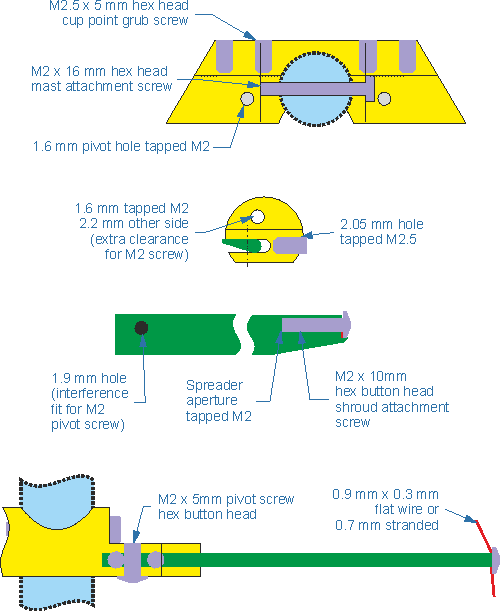
The general design and dimensions are illustrated here.
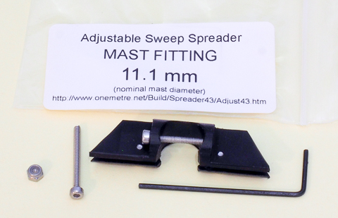
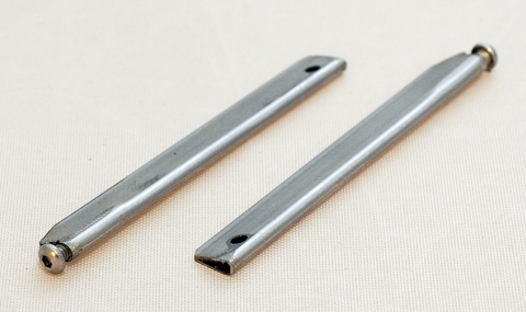
AssemblyThe mast fitting is machined from Acetal, and carries a pair of associated machined spreader bars.
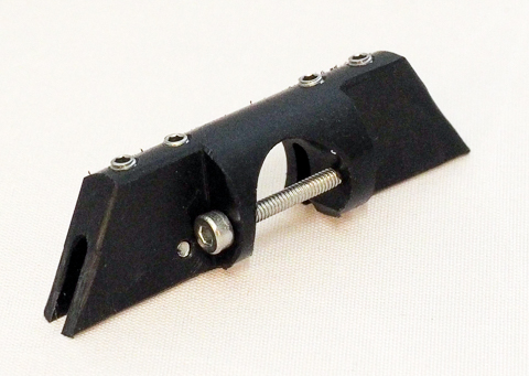
Note that one surface of the spreader bar has a red mark around the pivot hole. This surface with the red mark is considered "down" (see the side view of the general arrangement diagram, above). The assembled spreader cants at approximately 8 degrees and provides a lower drag entry to the apparent wind when the boat heels. The spreader is assembled by inserting the bars into the mast fitting slot with their "up" face uppermost and with their curved face forward and facing the grub screws, and screwing the pivot screws back into place. Note that the pivot hole in each bar is 1.9 mm to provide a close fit and no slack or slop in the pivot. The pivot screws are inserted from below the mast fitting, to prevent interference with the mast attachment screw. The pivot screw hex head requires a 1.3 mm hex key, and one is supplied in the retail packaging. Installation on the mastOne side of the mast fitting is threaded for the M2 attachment screw, while the other side is opened to 2.2 mm. A mast may not have its spreader attachment holes precisely centred, and the mast fitting may not attach despite the additional clearance. In this case, the mast fitting may be cut in two at its thinnest forward edge, allowing attachment to such a mast. Note that the forward edges should be chamfered to prevent the topping lift from snagging. If the assembled spreader requires frequent disassembly or detachment from the mast, it is possible that the threads in the Acetal body will deteriorate. The retail package provides an M2 x 20 mm mast attachment screw and an M2 lock nut to replace the 16 mm screw. If a longer attachment screw is used with the lock nut, the threaded side of the mast fitting should be drilled out to 2.0 mm. The mast attachment screw requires a 1.5 mm hex driver.
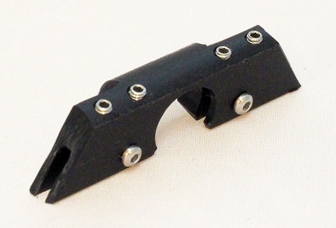
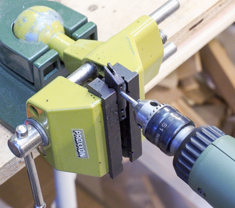
Note that the pointed outboard aft end of the mast fitting is required to overlap the spreader bar to prevent the topping lift from snagging when the bars are swept well back. Only trim, chamfer, or round this point if it is certain that significant sweep will never be required. Installation to the shroudsThe shrouds are pinched and clamped to the spreader bar by the M2 x 10 mm button head shroud retaining screw, which requires a 1.3 mm hex key (one key is included in the packaging). The end of the spreader bar is notched to accept the shroud, which should be located as shown in the earlier drawings and in the photos above. TuningThe objective of adjustable spreader sweep "V" is to give exceptionally fine control over mid-mast bend, and hence over mid-mast mainsail shape. This control requires adequate tension in the shrouds, since it is the spreader reacting against the shroud which allows the sweep to push the mast aft or pull it forwards as may be needed. Two grub screws control the position of a spreader bar by acting against the bar pivot, one on either side. Before making an adjustment, ease both grub screws for each bar. Then, where the spreader sweep pushes the mast aft, adjust the outer grub screw of each bar to obtain the desired sweep "V", and then to snug the inner grub screw lightly against the bar to keep it located. Conversely, where the spreader sweep is pulling the mast forward, adjust the inner grub screw of each bar to obtain the desired sweep "V", and then to snug the outer grub screw lightly against the bar to keep it located. The grub screws require a 1.3 mm hex key, and one is supplied in the retail packaging. Note that, by clamping the shrouds to the spreader bars and clamping the spreader assembly to the mast, the overall effective stiffness of the standing rigging is improved. Theoretical simulation of the mast / backstay / spreader / shrouds / forestay tensions as a system suggests a two-fold increase in effective stiffness. NotesDo not over-tighten any screws. While Acetal is a tough plastic, it does not have the strength of metal, and screw threads will strip. Similarly, while the spreader bars are steel, their spreader retaining ends are only approximately 50% threaded. Note that the clearance for the M2 lock nut, if used to secure the M2 x 20 mm mast attachment screw, is nominally 0 mm to the mast fitting upper surface. That is, it is designed to be held in place where a flat of the nut bears against the upper surface. The nut is therefore not free to rotate, making the attachment process easier. Package contents are: Acetal mast fitting, pair of spreader bars, 1.3 mm hex key, M2 x 16 mm hex socket head s/s mast attachment screw, M2 x 20 mm hex socket head s/s mast attachment screw, M2 s/s lock nut, 2 off M2 x 5 mm button head s/s pivot screw, 4 off M2.5 x 5 mm s/s cup point grub screw, 2 off M2 x 10 mm button head s/s shroud retaining screw. ManufactureIn case it is interesting, I've documented the batch manufacture of the Limited Edition. I tend to run Proxxon tools in my garage, so the cut-off saw is the Proxxon KGS-80, the lathe is the Proxxon PD-400, the mill is the Proxxon FF-500 fitted with the DA-3 3-axis DRO and the UT-400 dividing table, and the drill press is the Proxxon TBH with the Proxxon KT-150 X-Y table.
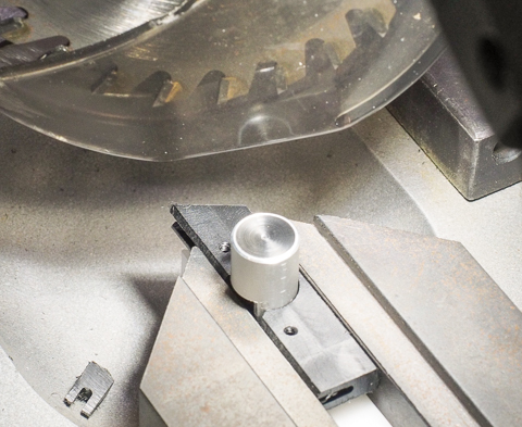
Step 1 is to cut off 48 mm lengths of 12.6 mm Acetal rod. I cut off 40 blanks, intending a batch of 30 finished fittings. As things turned out, I managed a batch of 28...
Step 2 is to mill the lower surface of the mast fitting. The hex key serves as a rough and ready parallel.
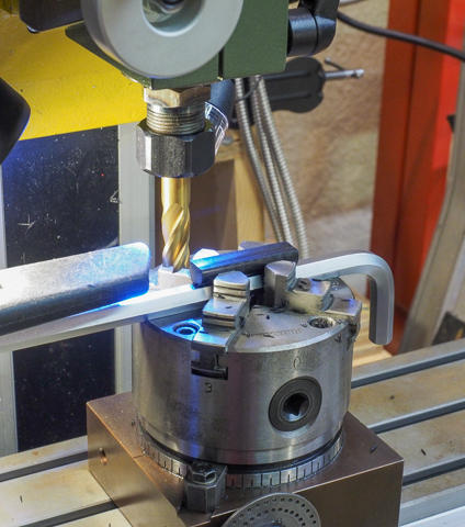
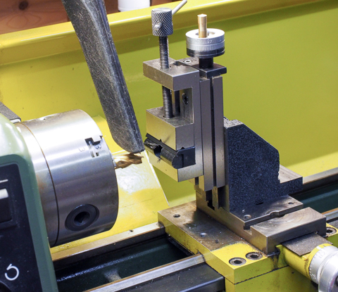
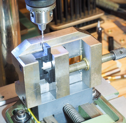
Step 4 is to mill the mast hole. There is no step 3, it is a later step after I trialled the process from start to finish. The fitting is clamped in a carrier. After trying to cut the mast hole in the milling machine with limited repeatability*, I used a vertical milling slide from Warco along with their matching small milling vice. The milling slide is the best inexpensive small slide I've found, but you'll need to look out for some gotchas. (1) The tool post mounting flange on the slide measured at 13.05 mm, and so would not fit my 13 mm toolpost. (2) To mount the slide directly on the lathe topslide I found the counterbores of the two mounting holes were not centred and had to be opened out to 9 mm from 8.5 mm (destroyed a 9 mm drill bit doing it). (3) After mounting, found I could not fit the vice from the top of the slide, the T slots were partially masked by the plate carrying the vice screw, and also found it was more or less impossible to fit the vice from the bottom, so I had to dismount the slide. (4) Skinned my finger while turning the slide adjusting wheel, the screw projects well beyond its fixing nut, it should be a dome nut. (5) The slide wheel turning handle unscrewed itself while turning the wheel. Apart from that, it worked reasonably well. (*) Repeatability was limited in the mill because the 11.1 mm cutter is actually 7/16" with a 3/8" shank, and the Proxxon system is entirely metric. Later editions of the FF-500 have an ER-20 nose (and there are 3/8" ER-20 collets), but my earlier edition has Proxxon proprietary collets, so I could not fit the cutter accurately. It did go into the drill chuck which fits the mill, but there was unacceptable run-out, probably because the chuck had a nominal 10 mm capacity and was not clamping the 9.7 mm shank of the 11.1 mm cutter adequately.
Step 5 is to chamfer the mast hole so that the fitting snaps nicely onto the mast. No photo for that, but the chamfer uses the same set-up as is shown in the next photo, Step 6, to mill the upper surface leaving the mast attachment lug in place.
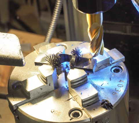
Step 7 is to drill the pivot holes. A carrier jig enables precise centring of the fitting.
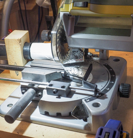
Step 8 is to saw off the 30 degree fitting end chamfer to prevent topping lift snagging. Well, it should have been step 8, but a senior moment decided to delay it until after step 10. That was when I lost 8 of the "extra" fittings when trying to saw off the end after I had cut the slot. It turned out the trailing slotted edge was inadequately supported and the last bit of the Acetal rod would snap away as the saw blade approached.
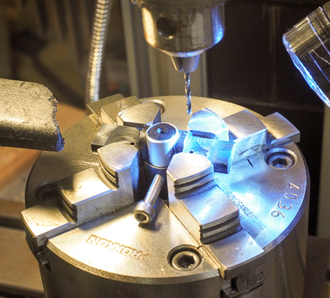
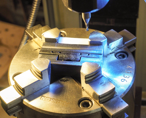
Step 9a is to drill the mast attachment holes, and again this needed a carrier to ensure the holes were precisely centred.
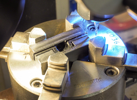
Step 9b is to slot the fitting to take the spreader bars. I was fortunate to find a 2 mm ball nose cutter with a cutting depth of 7.5 mm, most 2 mm milling cutters allow depths up to around 5 or 6 mm.
Step 10 is to drill the grub screw holes for the M2.5 grub screws. I used a 2 mm milling cutter rather than the more usual 2.05 mm tapping drill to get a tighter fit.
Step 10c is to tap the various holes, this photo illustrating tapping the grub screw holes. I used a Proxxon MIS-1 industrial assembly line torque controlled screwdriver, more usually used to screw down PCBs.
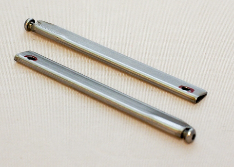
Step 11 is to cut lengths of spreader bar. The bar from SAILSetc is exactly 306 mm, and I wanted a mix of 40 mm, 50 mm, and 60 mm bars. The saw kerf was 1.8 mm, so each bar was in fact around 1 mm short of nominal. I needed a spreadsheet to tell me (!) that a two 306 mm lengths would yield 6 pairs of 40 mm and 6 pairs of 60 mm nominal, while another two lengths of 306 mm would yield 12 pairs of 50 mm nominal.
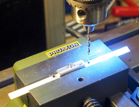
Step 12a is to drill the pivot holes in each bar. Each hole had to be (carefully!) made using a 1.5 mm milling cutter, and then a 1.9 mm drill bit would open it out as required. A lot of drill chuck work here, with a drop of cutting fluid every time. The jig in the centre ensured that the holes were equidistant from the bar end.
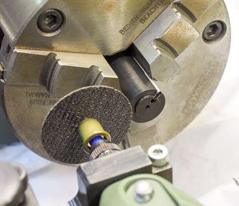
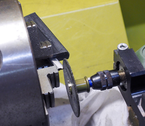
Step 12b is to tap the other end of the bar to M2. If I were to show a photo, it would be to show three snapped M2 taps embedded inside their bars. It turned out that tapping the 1.5 mm aperture in the bar required a drop of cutting fluid into the bar for every entry, a very steady hand with a lower torque setting on the Proxxon MIS-1 driver, running and backing the M2 taper tap first, then finishing with the M2 bottom tap which usually needed to be inserted by hand to start. I ended up using Dormer "Supercut" and the good quality taps from Model Fixings, who also supplied all the screws. Step 13 is to notch the bar end. A carrier positioned the bar precisely for the grinding operation. The Dremel cut-off discs on their "speedclic" mandrel worked very well. The lathe chuck was turned by hand to engage the grinding disc as needed.
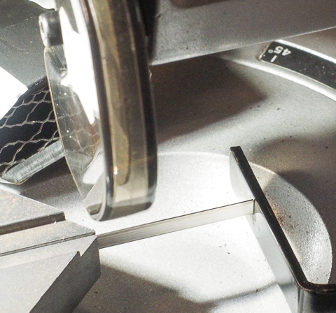
Step 14 is to chamfer the trailing edge of the bar near the shrouds, again to minimise topping lift snagging. Yet another carrier ensured precise alignment of the cutoff disc.
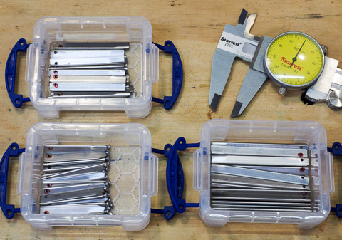
The final photo shows the various bars almost finished. A pointless addition is the Starrett vernier gauge in the photo, except to pay homage to its excellence. Digital gauges are great until their battery runs out (they seem to last around a week!), so I invested in the Starrett.
Batch manufacturing was an interesting exercise for me. I found that, while the fittings and bars in themselves took around 20 hours to machine from start to finish, preparing and refining the jigs and carriers needed at every step to ensure repeatability took close to 40 hours... 2015-08-11 |
|
©2025 Lester Gilbert |