|
I've been puzzling about having the right twist set into the mainsail as it
sheets out for the reach, and then having the twist pulled back out for the
run. (Prompted by the graph showing
that, due to the wind gradient, more twist is needed on the reach than
close-hauled or running.) This is my first idea for setting up a kicking
strap that eases the boom for the reach, then tightens it for the run. I'm
not certain of its practicality, but the geometry behind it seems valuable.
The diagram shows a kicking strap whose attachment to the base
of the gooseneck is via a pulley and length of line tied to a plate. The
idea is that the kicking strap moves in an arc of an ellipse. As it does
so, because the length of line is attached at two separate points on the plate,
the effective length of the kicking strap increases. These two points are
known as the foci of the ellipse, and are 22.8 mm apart for the particular
sheeting arrangement shown. The diagram also shows that the two foci are
not co-linear with the boom pivot point, but offset from the pivot, by 3.5
mm. This has the vital effect of shortening the effective kicking strap
length quite sharply once the boom has sheeted out beyond 55 degrees or
so. (The usual caveats apply: in the IOM class, this arrangement
probably is not legal.)
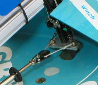
The picture shows the arrangement in my boat. It certainly runs nicely
-- but I'm not completely sure that it in fact does what it is supposed to do --
ease the kicking strap for the reach, and then tighten it up for the run.
Maybe the mast camera will help decide.
The spreadsheet (about 44 kb) illustrates how the
effective length of the kicking strap changes with boom rotation (ie sheeting
angle). The particular graph, below, assumes you start with 4 degrees of
twist set into your mainsail at the middle batten. The twist is eased to a
maximum of about 13 degrees at 50 or 60 degrees sheeting, and then the leech is
tightened right down again beyond that.
The spreadsheet allows you to vary the parameters of the ellipse
("a" and "b") in order to derive useful positions of the
foci and useful offsets of the foci from the boom pivot. It also
calculates the length of line needed, given the ellipse parameters and an
estimate of the pulley diameter. In the example here, a = 23 and b = 20
("a" must always be greater than "b", and both must always
be larger than 1). The offset is entered as a negative number, since it is
on the "other" side of the ellipse arc. Finally, the spreadsheet
allows you to enter your close-hauled twist, and then calculates what happens as
the boom moves out.
Note that the amount of the offset is quite critical. As you play with
the spreadsheet, you'll see that there is a very marked difference, for example,
between an offset of 4 mm and one of 3 mm, and both are quite different from the
"desired" offset of 3.5 mm!
Will Gorgen has had a play with the spreadsheet, and adapted it for his
Fairwind. His resulting graph is very interesting, and this is how he
explains it. (Note that Will calls the line through the pulley a
"bridle", and what I've called "focus distance" Will calls
"lateral lead distance" or "bridle endpoints".)
Well, once again your idea has caused me to whittle away a big chunk of
time exploring the design space... (smile). Here is what I did. The
geometry is for my Fairwind. I started with an initial close hauled twist of
3.7 degrees (about what you decided would be idea in your article on twist and
wind gradient). I systematically varied the offset from -2 mm to
-.75 mm. For each offset setting, I varied the lateral spacing of
the bridle endpoints from 12 mm to 2 mm. For each combination
of offset and lateral lead spacing, I adjusted the length of the bridle until
the twist on the run (sheeting angle of 90 degrees) is as close to 0 as
possible. I recorded the maximum middle twist that occurs on the reach.
I plotted the maximum twist versus lateral bridle lead spacing. Each curve
represents a fixed level of offset. The results are summarized on the chart.
The results are very interesting. For very small offsets, the maximum
reaching twist is quite insensitive to lateral lead spacing. For large
offsets, the maximum reaching twist is highly sensitive to lateral lead
spacing. For small lateral lead offsets, the bridle gets really short
making it impractical. For large lateral lead offsets, the bridle gets
really long leaving little space for the adjustment screw portion of the
kicking strap.
So here are the design implications. Assuming you have a design goal of
about 11.5 degrees of maximum middle twist (based on your article of twist and
wind gradient), you can achieve this in two different ways. You can either
adjust the lateral lead spacing for a given offset, or you can adjust the
offset for a given lateral lead spacing. I would lean toward having a
fixed lateral lead spacing based on a spacing that yields a practical bridle
length (I have chosen 8 mm which gives me a nice sized bridle). I
would make the offset rather small (my design point on the graph is
-0.8 mm, but it should actually be just slightly larger than that, say
0.85 mm or so). I would design a precision adjustment for the
offset. I'm thinking of a small adjustment screw to move the plate fore
and aft. Once you get a setting that you like, you could lock it down
the way you have designed it (the screw on the bottom of the gooseneck.
Of course now you have the ability to adjust the twist profile for different
degrees of wind gradient. On light wind days, I would tighten the bridle
lead a bit (5 to 10 mm) which eliminates the sharp "untwisting"
at high sheeting angles, which should prevent the problem of the sail fighting
the kicking strap and preventing the system from easing easily on the run (try
shortening the bridle length in the spreadsheet to around 40mm and see what
the twist profile looks like).
Will's analysis sounds spot-on to me.
2005-12-18 |